
User's Manual


HARSFEN0602
The scheduled case is explained in the section on “Gain Scheduling”.
The parameter GS[0] helps stabilizing the motion in very slow speeds. It cuts the proportional gain of the
speed controller after enough controller sampling times elapsed without a change in the encoder readout.
Consider for example a 200-count/sec, speed reference. A new encoder count is available once per 5 msec –
which are about 25 sampling times of the speed controller. If a new encoder pulse comes only once per 5
msec, then the speed readout is delayed by at least 2.5msec, which in turn may have fatal effect on the
control stability. Setting GS[0]=12, the proportional gain of the controller is applied only for about half of
the time, leading to a practical reduction of the proportional gain to half at that speed. The reduced gain
implies reduced bandwidth and increased stability. The price is a slow acceleration from a complete rest. To
avoid the cutting of the speed proportional gain, set GS[0] to its maximum value – refer the GS command in
the Command Reference Manual.
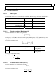
The parameters of the non-scheduled speed controller are:
Parameter Description
KP[2] Proportional gain
KI[2] Integral gain
GS[0] Proportional gain duration
GS[2] Controller gain selection
GS[14] Speed reference integral threshold
FF[1] Torque feed forward
CL[1] Continuous torque limit
PL[1] Peak torque limit
KV[N] High order filter parameters
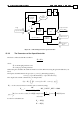
15.3 The Position Controller
15.3.1 Block Diagram
The position controller is made of a proportional gain, cascaded over the speed controller. The block
diagram of the position controller is given in Figure 41. The reference to the speed controller is composed of
the derivative of the position command (speed) and of the output of the auxiliary position controller. The
derivative of the position command is multiplied by the FF[2] factor, in order to eliminate the tracking errors
when the speed is steady.
The gain scheduler can be used, or the gains of the controller may be fixed.
The high order filter can be used, or not.
To fix the controller gains, set GS[2]=0.
To avoid the use of the high order filter, set KV[0]=0.
The same controller is used for the single feedback mode (UM=4) and for the dual feedback mode
(UM=5). Use the single feedback mode when there is only one sensor in the system, for
commutation, speed, and position sensing. Use the dual feedback mode when the load is driven
through a gear, where a separate load sensor enables precise load positioning in spite of some
backlash and gear compliance.