
User's Manual


HARSFEN0602
RLS and FLS can be read by the user program and activate their
corresponding automatic routines, but they do not affect the motion
immediately.
The position referencing limits VH[3] and VL[3] become ineffective.
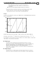
! If the modulo value is selected low, and the sensor speed is high, more than one full
revolution of the position counter may elapse within a single sampling time.
This will cause the position counter to behave in an unpredictable way.
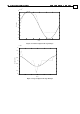
Example:
Consider a motor rotating in the constant speed of 4000 counts/sec, with XM=2000. The PX variable will
behave as depicted below.
0 0.5 1 1.5
-1000
-500
0
500
1000
Time (sec)
Main
Position (PX)
The PX variable changes in the range [-XM/2 … XM/2-1], which is in this example [-1000..999].
The largest possible modulo is
31
2
. With this modulo setting, PX varies in the range [ 12..2
3030
−− ].
The variable PY counts the distance traveled by the auxiliary encoder. The PY variable is counted modulo
YM, similarly to the way PX counts modulo XM.
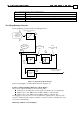
13.2 Digital Inputs
The Harmonica has 6 digital input pins. The digital input pins must be associated to
functions before being used. All the digital input pins can be associated to the Enable, Stop,
RLS, FLS, and Begin functions. Two of the digital inputs are connected to high-speed
hardware counters. These inputs can also associate to the Home function.
The association of input pins to functions is described in detail in the Command Reference
Manual, the IL[] command.
13.3 Digital Outputs
The harmonica has two digital output pins. The digital output pins must be associated to a
function before being used. The functions may be general purpose output, Amplifier Ready