
User's Manual


HARSFEN0602
The stepper unit mode enables the rotation of a motor without feedback control. The motor field is
rotated to the desired direction, and the rotor magnet is believed to follow. The user must not rotate the
field too abruptly in order that the rotor will be able to track its desired direction. If the rotor misses a
full electrical revolution, it will be attracted to a wrong electrical equilibrium, with no feedback to
correct that.
Moreover, if the field rotation is stopped abruptly, the motor will not properly brake. If the rotor misses
half an electrical revolution, it will start accelerating – and the net braking torque sum over an electrical
revolution is zero.
Specifying higher motor current enables larger accelerations and decelerations, but also lose more power
at the steady state.
In the stepper mode, most of the time the stator field and the rotor magnet are near equal, and the motor
efficiency is very low.
The Harmonica uses the stepper mode mainly for safe testing and controller tuning before any feedback
control is tuned. The Harmonica can serve as an advanced micro-stepper driver, with 1024 micro-steps
per electrical revolution. The main limitation is that the Harmonica is a 3-phase driver, while most the
stepper motors in the market are two-phased.
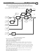
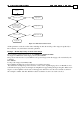
The block diagram of the micro-stepper mode UM=3 is depicted below:
Software
position
command
Enable if
RM==1
Stepper angle
command
WS[20]
Torquecommand
(DV[1], Amp)
Auxiliary position
command
Stop
manager
Stop and limit
switches
Smoother
Torque
command
Current
controller
1024 count
per electrical rev.
Figure 21: Stepper mode (UM=3)
The stepper angle command is generated by:
The position software command generator
The position auxiliary command generator
The position Stop Manager
The generation of the stepper angle command is similar to the position command generation
in UM=5, and will be described in "Stop management" below.
The torque command is simply given by the command TC.
11.4 The Dual feedback mode: UM=4
The dual feedback mode is used when different sensors are used for speed/commutation and
for position. This is a common situation if the motor drives the load through a reduction
gear. The controlled position is that of the load. The load position, however, may not be
good for commutation or speed feedback, since: