
User's Manual


HARSFEN0602
11.2 Speed mode: Unit mode 2
In this mode the amplifier controls the motor speed by feedback. The speed controller demands
torque from the current controller.
The reference to the speed controller is summed from a software commands, and an auxiliary
speed command. The auxiliary speed command is derived using the analog input, the auxiliary
encoder input, and the ECAM table – details are given below.
The Stop digital input and the limit switches (RLS,FLS) can be used to stop or to limit the
direction of the motor – see the paragraph on stop management below.
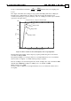
The amplifier will abort upon over-speed, as specified by the parameters LL[2] and HL[2].
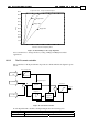
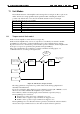
The speed control scheme is depicted below:
Software speed
command
Enable if
RM==1
Speed command
(DV[2], cnt/sec)
Software speed
feedback
-
Torquecommand
(DV[1], Amp)
Auxiliary speed
command
Stop
manager
Stop and limit
switches
Smoother
Speed
controller
Figure 16: Unit mode 2 (Speed) structure
If you are not using the analog input for torque command, set RM=0, to avoid that noises
and offset will affect the amplifiers speed command.
The DV[2] command reports the combined (software and analog input) speed demand.
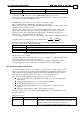
11.2.1 The software speed command
The software speed command generator generates speed commands, subject to acceleration,
deceleration, and to speed limits. The following commands are relevant to the generation of
the software speed command:
Command Description
AC Profiler acceleration limit. Units counts/sec
2
.
BG Begin command
DC Profiler deceleration limit. Units counts/sec
2
.
EM EM[1]=1 use ECAM table, EM[1]=0 do not use
JV Profiler final speed command. Units counts/sec.
PM Set PM=0 to remove the acceleration limits from the software speed command.
PM=0 is used by the Composer program in the process of tuning the speed
controller, but in normal operation we advise not to program PM.