
User's Manual


HARSFEN0602
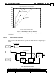
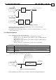
Feedback IQ ID
Output VQ VD
The saturation is given by 0.5TS/
3
1025⋅ , where TS is the current controller sampling time
in usec and
3
1025⋅ is the period of the 40mHz PWM generator clock in usec.
The division of the proportional and the integral gains by the DC voltage is since the output
of the current controller is PWM duty cycle.
The PWM duty cycle sets the corresponding motor terminal voltage to
Motor terminal voltage = (PWM duty cycle)
(DC power voltage)
It is seen from the equation above that the uncertainty in the DC power voltage acts as a gain
uncertainty for the current controller.
The DC power voltage varies a lot – it goes down in high current because of the power
supply output impedance. It increases when upon braking the motor acts as a generator.
The division in the bus voltage makes the output of the controller proportional to the
physical motor voltage, eliminating the uncertainty.
The bus voltage is filtered, to avoid too rapid changes of the current loop PI parameters. The
bus voltage filter is a simple low-pass, with a bandwidth of
32768
]4[XP
log
TS
8
10
6
⋅π
−
Hz.
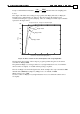
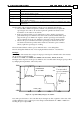
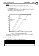
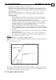
The relation between XP[4] and the time constant of the filter is calculated in the table
below for several values of XP[4], and TS=50.
XP[4] Bus voltage filter bandwidth, Hz
31750 25Hz (High impedance supply)
30720 (factory set) 50Hz
28900 100Hz (Low impedance high ripple supply)
Table 10-1: Bandwidth selections for bus voltage filter
XP[4] is factory set to 30720.
Set higher XP[4] if the output impedance of your power supply is too high, causing interplay
between the filter gains and the DC motor voltage.
Set lower XP[4] if you have very low impedance power supply, but high ripple voltage.
In normal applications, we recommend not to change the factory setting of XP[4].
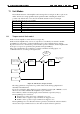
10.3 Current amplifier protections
The current amplifier and the power stage have several protections, detailed in this section.
When one of the protections is activated, the amplifier shuts immediately. If brake action is
defined (Refer the OL[] and BP[] commands), the brake is immediately activated. In the
next 10msec the amplifier will not set the motor on, even if instructed to do so.
You can know that an amplifier has been shut down by a protection by:
Observing the Motor-On and the Fault bit in the SR report, or in the CAN special
status object.
Mapping the Motor Fault event to an event-driven CAN PDO.
Polling the MO variable (drops to 0 on exception)
Polling the MF variable (Reports a non zero value after an exception has been
trapped).
Mapping a digital output to AOK – refer the OL[] command.
You may install in your user program an AUTO_ERR routine to automatically respond an
exception shutdown.
The protections are:
Protection MF reports Reason
Over voltage 0x5000 The voltage of the power supply is too high, or the servo
drive did not succeed in absorbing the kinetic energy while
breaking a load. A shunt resistor may be required.
The over voltage threshold differs with the power stage