
User's Manual


HARSFEN0602
0 2 4 6 8 10 12 14 16
0
500
1000
1500
2000
2500
3000
3500
4000
4500
5000
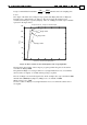
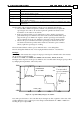
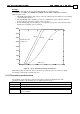
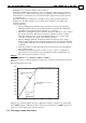
Current Controller Sampling Times
Amp
Torque Cmd Vs. Torque Controller Input
XP[5]=400
XP[5]=1000
XP[5]=5000
Figure 13: Rate limiting for the torque input filter
We recommend not to change the factory setting of XP[5] and XP[6] in standard
applications.
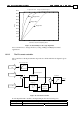
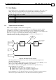
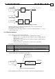
10.2.2 The PI current controller
The controllers for the IQ and the ID components are similar. Their block diagram is given
below.
Kp[1]/VB
KI[1]/VB
-
Feedback
Command
∑
k
k
Integrator
Proportional gain
Integral gain
Saturation
Anti wind up
Output
Bus voltage
VB
Bus Voltage Filter
Figure 14: Current PI controller
For the IQ and the ID controllers, the Inputs/Outputs have the following roles:
Parameter Q controller D controller
Bus voltage Measured & filtered motor power DC voltage
Command Torque command 0