
User's Manual


HARSFEN0602
With continuous commutation all the three motor coils are powered simultaneously to yield
a magnetic field exactly at the direction of the rotor. This brings
ε near zero continuously,
with minimal torque losses and ripple torques.
The continuous commutation mode is native for the Harmonica and is used most of the time.
The continuous commutation is much more complex to implement then six-steps
commutation. In fact it requires two independent current controllers to control both the
amplitude and the direction of the windings magnetic field.
Continuous commutation reduces the dynamic demands from the current controller, since
current demands are almost never switched abruptly.
9.6 Winding shapes
The implementation of continuous commutation implies that we know how to direct the
magnetic field of the windings.
For a general motor, we have
))240(hI)120(hI)(hI(KT
bba
−θ+−θ+θ⋅=
With
T
Torque
K
Constant
h
Windings shape function.
cba
I,I,I
The A,B, and C phase currents respectively.
For optimal efficiency, it is easy to show that the phase currents must be
)240(hII),120(hII),(hII
0c0b0a
−θ=−θ=θ= for some value
0
I .
(1)
In another words, the phase currents must be proportional to the corresponding commutation
function values. If (1) is satisfied, the magnetic field produced by the winding currents is
perpendicular to the rotor magnet.
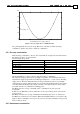
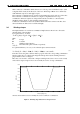
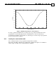
Most motor are wound to sinusoidal or Trapeze winding forms, but no motor can be exactly
sinusoidal or trapeze. Trapeze motors are normally chosen for six-step commutation,
whereas sinusoidal motors are normally chosen for continuous commutation.
Figure 8: Winding shape function for a Trapeze motor
0 50 100 150 200 250 300 350 400
-0.4
-0.3
-0.2
-0.1
0
0.1
0.2
0.3
0.4
Theta (degrees)
h(theta)