
User's Manual


HARSFEN0602
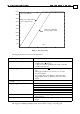
hardly noticeable in low speed, significantly looses motor torque at high speed.
If Hall sensors are not present, and if the commutation is performed using an incremental
encoder, then upon motor start the Harmonica must first find the electrical direction of the
motor.
If digital Hall sensors are not present (CA[20]=0), then at motor on, a commutation search is
made. The commutation search is described in the section "Commutation search".
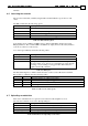
The following seven parameters describe the Hall sensors:
CA[1] The polarity of the A digital Hall sensor. 1 for active high, 0 for active low.
CA[2] The polarity of the B digital Hall sensor. 1 for active high, 0 for active low.
CA[3] The polarity of the C digital Hall sensor. 1 for active high, 0 for active low.
CA[4] The actual Hall sensor connected to the A Hall connector pin 1 for A, 2 for B and 3
for C
CA[5] The actual Hall sensor connected to the B Hall connector pin 1 for A, 2 for B, and 3
for C
CA[6] The actual Hall sensor connected to the C Hall connector pin 1 for A, 2 for B, and 3
for C
CA[7] The offset of the digital Hall Sensors in encoder units. The range for this parameter
is [0..CA[18]-1]. This parameter compensate for deviations in the hall sensor
switching point.
If no encoder is present, set this parameter to zero.
CA[20] Digital Hall sensors present.
0: No digital Hall sensors are connected
1: Digital Hall sensors are connected.
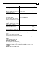
9.3.4.3 Encoder parameterization
Accurate commutation requires high a resolution sensor. Many types of high-resolution
sensors exist. The selections available for Harmonica are:
CA[17] Commutation sensor type.
1: Main Encoder
CA[21] Position sensor present
0: No high-resolution commutation sensor. Commutation will be done based on the
digital Hall sensors only.
1: The main position sensor shall be used for commutation
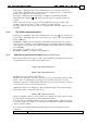
The encoder is normally used both for motion feedback and for commutation. As a motion
feedback counter, it must count up when the motor go forward in the application sense. As a
commutation counter, it must count up when the commutation angle increases.
The above two requirements are not necessarily same, so we need the following two
parameters:
CA[16] Encoder direction: Set 0 or 1 so that the encoder will count forward in the desired
movement direction.
CA[25] Motor direction: Set 0 or 1 so that with positive torque, the motor will rotate in the
direction for which the encoder counts up.
The encoder measures the shaft angle. In order to commutate, we must know the encoder
count per an electrical revolution. Normally, the number of encoder counts per motor
revolution is an integer (If not, we may not be able to commutate correctly with an
encoder...). The number of pole pairs per revolution is always integer. By knowing the
encoder counts per mechanical revolution, and by knowing how many pole pairs are within
a revolution, the commutation counter can infinitely update without accumulating errors.
For linear motors, it is best to set the number of pole pairs CA[19] as the largest number of