
User's Manual


HARSFEN0602
At that very instance the Hall sensors read the electrical angle accurately.
After the first Hall sensor switch, the commutation is kept accurate by updating the
commutation counter incrementally using the shaft position sensor.
9.3.3.2 Detecting commutation errors (loss of feedback)
After commutation by the encoder starts, there exist two sources for the electrical angle
measurement. There is the high-resolution measurement by the encoder, and also the low
resolution, but reliable digital Hall sensor readout.
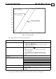
The digital Hall sensor readout defines a range in which the high resolution calculated angle
should reside. Deviating from this range by more than few degrees results in declaring a
commutation error and automatic motor shut down.
The allowed deviation is increased in higher speeds, since there the sensor and the
calculation delays contribute a significant matching error.
The most common causes for commutation loss are:
- A slit in the encoder disk is clogged with dirt. When this happens, an encoder of 4000
counts/rev may count for example 3999 counts/rev. After enough revolutions, the
cumulative error is large.
- Speed to fast relative to the defined encoder filer, and encoder pulses are lost.
- An interpolator derives the encoder A/B pulses. Some interpolators send, from time to
time, pulse batches of much higher frequency then the motor speed. Avoid using the
encoder filter with interpolators even if you think that the motor speed shall be slow
enough.
9.3.4 Parameterization of the commutation and the commutation sensors
9.3.4.1 Winding order
The Harmonica has three motor connection pins, named A, B, and C.
The pin names are not rigidly tied to their actual role. The harmonica can define internally
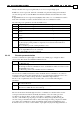
which motor phase is connected to which output pin. The parameter CA[25] controls the
connection:
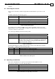
CA[25] Phase A connected
to pin
Phase B connected
to pin
Phase C connected
to pin
0 A B C
1 A C B
As seen in the table, changing CA[25] switches the B and C phases.
Actually, changing CA[25] will reverse the direction to which the motor moves for a given
torque command.
9.3.4.2 Hall sensors parameterization
Figure 6 presents an idealized picture of the digital Hall sensor reading. All the waveforms
are in their precise phase and precise polarity.
In practice, the results of the figure may not equal what we see immediately after connecting
the motor and its sensors to the Harmonica.
- The Hall sensors must be matched to the motor coils. Possibly the order of
connecting the Hall sensors to their respective connector pins is incorrect, or the
motor phase connections has been switched as describe above to modify the
motor direction.
- The Hall sensors may be active high or active low. For some Hall sensor
arrangements (known as
30 arrangements) two sensors may be active high, and
the other one is active low, or vice versa.
In addition, the switching lines in the figure are set in 30,90,150,210,270, and 330 degrees.
The even spacing of 60 is true for most motors, but many motors exhibit a significant
origin deviation: for example, with 10 degrees deviation, the digital Hall sensor switching
points may be at 40,100,160,220,280,and 340 degrees respectively. This error, although