
user manual


3.4.6.4 Pulse-and-Direction Input Option on FEEDBACK B
(YA[4]=0)
This mode is used for input of differential or single-ended pulse-and-direction position
commands on Port B1. In this mode Port B2 provides differential buffered pulse-and-
direction outputs for another axis.
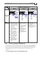
Below are the signals on the Auxiliary Feedback ports when set up to run as a single-ended
pulse-and-direction input:
Port Pin Signal Function Pin Position
B2 10 CHAO Channel A output
B2 11 CHAO- Channel A complement output
B2 12 CHBO Channel B output.
B2 13 CHBO- Channel B complement output
14 NC Do not connect this pin
15 NC Do not connect this pin
PWR
18 SUPRET Encoder supply voltage return/
COMRET
B1 19 PULS/CHA Pulse/Auxiliary channel A high
input
26 Pin D-Sub
High Density Plug
20 NC Do not connect this pin
B1 21 DIR/CHB Direction/Auxiliary channel B
high input
22 NC Do not connect this pin
23 NC Do not connect this pin
24 NC Do not connect this pin
PWR 25 +5V Encoder supply voltage
26 Pin D-Sub Socket
Note: In models not containing absolute encoder support, it is possible to use
terminals 16 and 17 for SUPRET connections.
Table 3-11: Single Ended Pulse-and-Direction Auxiliary Encoder Pin Assignment on
FEEDBACK B
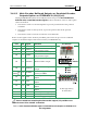
FEEDBACK B on the “top” of the Drum has a 26-pin high density D-sub socket. Connect the
Auxiliary Feedback cable from the Pulse and Direction Controller to FEEDBACK B using a
26-pin, high density D-Sub plug with a metal housing. When assembling the Auxiliary
Feedback cable, follow the instructions in Section 3.4.3 (Feedback Control and
Communication Cable Assemblies).
J4
Female
Drum Installation Guide Installation
MAN-DRUIG (Ver. 1.0)
3-36