
user manual

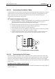


Incremental Encoder
Interpolated Analog
Encoder
Resolver
Tachometer and
Potentiometer
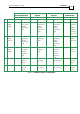
DRU XX/YYY_ DRU XX/YYYI DRU XX/YYYR DRU XX/YYYT
Pin Port Signal Function Signal Function Signal Function Signal Function
22 B1 – Aux.
Input/
Output
CHB- Main channel
B low output/
Auxiliary
channel B low
input
CHB- Emulated
channel B low
output/
Auxiliary
channel B low
input
CHB- Emulated
channel B low
output/
Auxiliary
channel B low
input
CHB- Emulated
channel B
low
output/
Auxiliary
channel B
low input
23 B1 – Aux.
Input/
Output
INDEX Main INDEX
high output/
Auxiliary
INDEX high
input
INDEX Auxiliary
INDEX high
input
INDEX Emulated
INDEX high
output/
Auxiliary
INDEX high
input
INDEX Auxiliary
INDEX
high input
24 B1 – Aux.
Input/
Output
INDEX- Main INDEX
low output/
Auxiliary
INDEX low
input
INDEX- Auxiliary
INDEX low
input
INDEX- Emulated
INDEX low
output/
Auxiliary
INDEX low
input
INDEX- Auxiliary
INDEX
low input
25 PWR +5V Encoder/
Hall +5V
supply
+5V Encoder/Hall
+5V supply
+5V Encoder/
Hall +5V supply
+5V Encoder/
Hall +5V
supply
26 PWR +5V
Encoder/
Hall +5V
supply
+5V Encoder/Hall
+5V supply
+5V Encoder/
Hall +5V supply
+5V Encoder/
Hall +5V
supply
Table 3-7: Feedback Cable Pin Assignments
Drum Installation Guide Installation
MAN-DRUIG (Ver. 1.0)
3-18