
user manual

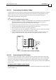


Use only a D-sub connector with a metal housing.
Attach the braid shield tightly to the metal housing of the D-type connector.
On the motor side connections, ground the shield to the motor chassis.
On controller side connections, follow the controller manufacturer’s
recommendations concerning the shield.
Figure 3-9: Feedback and Control Cable Assemblies
Note: All D-sub type connectors, used with the Drum, should be assembled in this way.
3.4.4 Main Feedback Cable (FEEDBACK A)
The main feedback cable is used to transfer feedback data from the motor to the drive.
The Drum accepts the following as a main feedback mechanism:
Incremental encoder only
Incremental encoder with digital Hall sensors
Digital Hall sensors only
Incremental Analog (Sine/Cosine) encoder (option)
Resolver (option)
Tachometer & Potentiometer
Absolute Encoder
FEEDBACK A on the “front” of the Drum has a 26-pin high density D-sub socket. Connect the
Main Feedback cable from the motor to FEEDBACK A using a 26-pin, high density D-Sub
plug with a metal housing. When assembling the Main Feedback cable, follow the instructions
in Section
3.4.3 (Feedback Control and Communication Cable Assemblies).
Note: the Feedback connector also supports Feedbacks A and B.
Metal Housing
Make sure that the braid shield is in
tight contact with the metal housing
J4 Female
Drum Installation Guide Installation
MAN-DRUIG (Ver. 1.0)
3-15