
User Manual

12
| www.gd-elmorietschle.com © Gardner Denver Schopfheim GmbH, Gardner Denver Deutschland GmbH
Set up and operation
F
F
A
E
M
M
O
I
1
K
1
H
1
K
H
I CD
B
A
Q
N P
P
1
Z
U
1
D
1
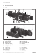
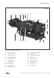
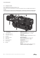
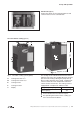
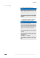
Fig. 2 Vacuum pump S-VSI 100
4 Set up and operation
4.1 Setup
A Vacuum connection
B Exhaust air outlet
C Cooling water inlet G
3
/
8
D Cooling water outlet G
3
/
8
D
1
Cooling water drain
E Cooling air inlet
F
Cooling air outlet
H, H
1
Oil fi lling point
I, I
1
Oil sight glass
K, K
1
Oil discharge point
M Oil recommendation plate
N Data plate
O Rotation direction plate
P
Drive motor
P
1
Motor data plate
Q
hot surfaces > 70°C
U
1
Vent valve
Z
Outlet silencer
S-VSI (01)