Edition: 1.9.
Table of contents Table of contents 1 Foreword . . . . . . . . . . . . . . . . . . . . . . . . . . . . . . . . . . . . . . . . . . . . . . . . . . . . . . . . . . . . . . . . . . . 4 1.1 1.2 1.3 1.4 1.5 1.6 1.7 1.8 Principles . . . . . . . . . . . . . . . . . . . . . . . . . . . . . . . . . . . . . . . . . . . . . . . . . . . . . . . . . . . . . . . . . . . Target group . . . . . . . . . . . . . . . . . . . . . . . . . . . . . . . . . . . . . . . . . . . . . . . . . . . . . . . . . . . . . . . . .
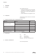
Table of contents 6 Commissioning and decommissioning . . . . . . . . . . . . . . . . . . . . . . . . . . . . . . . . . . . . . . . . . . 23 6.1 6.2 6.3 Commissioning . . . . . . . . . . . . . . . . . . . . . . . . . . . . . . . . . . . . . . . . . . . . . . . . . . . . . . . . . . . . . . 6.1.1 Checking the rotation direction. . . . . . . . . . . . . . . . . . . . . . . . . . . . . . . . . . . . . . . . . . . Decommissioning/ storing . . . . . . . . . . . . . . . . . . . . . . . . . . . . . . . . . .
Foreword 1 Foreword 1.1 Principles These operating instructions: 1.2 • are a part of the following screw vacuum pumps S-VSI 100 (01), S-VSI 300 (01) and S-VSI 300 (12). • describe how to use them safely and properly in all life phases. • must be available where the equipment is used. Target group The target group for these instructions is technically trained specialists. 1.3 Supplier documentation and accompanying documents Document Contents No.
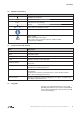
Foreword 1.6 Symbols and meaning Symbol Explanation Condition, pre-requisite #### a), b),... Instructions, action Instructions in several steps Results [-> 14] Cross reference with page number Information, note Safety symbol Warns of potential risk of injury Obey all the safety instructions with this symbol in order to avoid injury and death. 1.
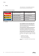
Safety 2 Safety The manufacturer is not responsible for damage if you do not follow all of this documentation. 2.1 Warning instruction markings Warning Danger level Consequences if not obeyed DANGER immediately imminent danger Death, severe bodily injury WARNING possible imminent danger Death, severe bodily injury CAUTION possible hazardous situation Slight bodily injury possible hazardous situation Material damage NOTICE 2.
Safety 2.3 Designated use The machine must only be operated in such areas as are described in the operating instructions: • only operate the machine in a technically perfect condition • do not operate the machine when it is only partially assembled the machine must only be operated at an ambient temperature and suction temperature of between 5 and 40°C. Please contact us for temperatures outside this range.
Safety 2.5 Personal qualifications and training • Ensure that people entrusted with working on the machine have read and understood these operating instructions before starting work, particularly the safety instructions for installation, commissioning, maintenance and inspection work.
Safety 2.8 2.9 Safety instructions for installing, commissioning and maintenance • The operator will ensure that any installation, commissioning and maintenance work is carried out by authorised, qualified specialists who have gained sufficient information by an in-depth study of the operating instructions. • Only work on the machine when it is idle and cannot be switched on again • Ensure that you follow the procedure for decommissioning the machine described in the operating instructions.
Transport, storage and disposal 3 Transport, storage and disposal 3.1 Transportation 3.1.1 Unpack and check the delivery condition a) Unpack the machine on receipt and check for transport damage. b) Notify the manufacturer of transport damage immediately. c) Dispose of the packaging in accordance with the local regulations in force. 3.1.2 Lifting and transporting WARNING Death or limbs crushed as a result of the items being transported falling or tipping over.
Transport, storage and disposal 3.2 Storage NOTICE Material damage caused by improper storage. Ensure that the storage area meets the following conditions: a) dust free b) vibration free 3.2.1 Ambient conditions for storage Ambient conditions Value Relative humidity 0% to 80% Lagertemperatur -10°C to +60°C The machine must be stored in a dry environment with normal air humidity. It should not be stored for more than 6 months. see Info “Machine storage guidelines”, Page 4 3.
Set up and operation 4 Set up and operation 4.1 Setup P1 O H M S-VSI (01) U1 F A H1 M E F K D1 I D C K1 N A B Z Fig.
Set up and operation S-VSI (12) P P1 O N H M U1 F H1 A E D M I1 F C K1 B Q I K D1 U Q Z Fig.
Set up and operation 4.1.1 Data plate 1 2 3 4 5 61 6& 7<3 96, (1 6 N: ,' PEDU DEV Pñ K PLQ 0DGH LQ *HUPDQ\ 5RJJHQEDFKVWUDVVH ' 6FKRSIKHLP 8 9 Fig. 4 7 1 Type/ Size (mechanical version) 2 Serial number 3 Year of construction 4 Item no. 5 Final pressure (abs.) 6 Pumping capacity 7 Speed 8 Motor output 9 Operating mode 6 Data plate 4.
Set up and operation 4.3 Areas of application The screw vacuum pumps are suitable for the evacuation of closed systems or for a continuous vacuum within the following intake pressure ranges: 0.1 to 1000 mbar (abs.). They are also particularly suitable for feeding in extremely damp gases. The water vapour compatibility is very high. The maximum pumping capacity with free suction is 110 m3/h and 320 m3/h at 50 Hz. Data sheet D 832 shows the dependency of the pumping capacity on the intake pressure.
Set up and operation 4.4 Cooling the machine 4.4.1 Continuous flow cooling (Standard version) With continuous flow cooling water flows continuously through the cavity in the double walled compressor housing. For safety reasons the cooling system should be fitted with a solenoid valve, temperature and a flow switch. The assembly group continuous flow water cooling (Fig. 5) as well as a special control unit are obtainable. U5 U4 U3 U1 D C U6 U2 Fig.
Set up and operation Control unit (option) Analyse the signals of the monitoring devices and control motor as well as solenoid valve. Fig. 6 Control unit (option) 4.4.2 Circulation cooling (option) F Y 580 mm F C2 E D2 65 0m m Fig. 7 Circulation cooling system (option) C2 Cooling water inlet G 3/4 D2 Cooling water outlet G 3/4 E Cooling air inlet F Cooling air outlet Y Display 580 mm The cooling circuit is fitted with thermostat-controlled three-way valves.
Installation 5 Installation 5.1 Preparing for installation Check the following points: • • • • • Machine freely accessible from all sides Do not close ventilation grids and holes Sufficient room for installing and removing pipes and for maintenance work, particularly for installing and dismantling the machine No external vibration effects Do not suck any hot exhaust air from other machines into the cooling system. The oil filling point (Fig. 2/H, H1), oil sight glass (Fig.
Installation 5.3 Connecting pipes a) Vacuum connection at (Fig. 2/A, 3/A). NOTICE Material damage resulting from the forces and torques of the pipes on the unit being too high. Only screw pipes in by hand. The pumping capacity of the vacuum pump is reduced if the suction pipe is too narrow and/or too long. b) The discharged air can be blown out through the exhaust silencer (ZSZ) at (Fig. 2/B, 3/B) or conducted away using a hose or a pipe.
Installation 5.4 Connecting the cooling water pipe NOTICE Cooling water control! The vacuum pump must not be operated without cooling water control. Danger breakdown of the pump Ensure that the cooling water stream is not interrupted. a) Connect the cooling water pipe to the cooling water inlet (Fig. 2/C, 3/C) and the cooling water discharge pipe to the cooling water outlet (Fig. 2/D, 3/D).
Installation b) When connecting a circulating cooling system to an external cooling system, it must be filled with cooling fluid. NOTICE Rinse the pipe network on the customer side before connecting it A filter element must be installed in the pipe network to prevent foreign bodies getting into the heat exchanger. Risk of frost damage in the cooling system Freezing cooling water may lead to extensive damage to the machine. Therefore mix the cooling water with at least 10 % of anti-freeze.
Installation 5.5 Filling with lubricating oil a) Fill the lubricating oil (for suitable sorts see „Maintenance“) for the gear teeth and the bearings into the oil filling points (Fig. 2/H, 2/H1) up to the middle of the inspection glasses (Fig. 2/ I, 2/I1). b) Close the oil filling points. 5.6 Connecting the motor DANGER Danger of death if the electrical installation has not been done professionally! The electrical installation may only be done by a specialist electrician observing EN 60204.
Commissioning and decommissioning 6 Commissioning and decommissioning 6.1 Commissioning WARNING Improper use May lead to severe or fatal injuries. Therefore be sure to obey the safety instructions. CAUTION Hot surfaces When the machine is at operating temperature the surface temperatures on the components (Fig. 2/ Q) may go above 70°C.
Commissioning and decommissioning 6.1.1 Checking the rotation direction The drive shaft direction of rotation is shown by the rotation direction arrow (Fig. 2/O) on the motor flange. a) Start the motor briefly (max. two seconds) to check the direction of rotation. When looking at the motor fan, it must rotate clockwise. NOTICE Incorrect direction of rotation Operating in the wrong direction of rotation leads to damage to the machine.
Maintenance and repair 7 Maintenance and repair DANGER Danger of death from touching live parts! Before maintenance work disconnect the machine by pressing the main switch or unplugging it and ensure that it cannot be turned on again. WARNING Hot surfaces and equipment During maintenance work there is the danger of getting burnt on hot components (Fig. 2/Q) and by the machine lubricating oil. Wait for the machine to cool down. 7.
Maintenance and repair 7.2 Maintenance work Interval Maintenance to be carried out Section monthly Check the pipes and screws for leaks and to ensure they are seated properly and if necessary seal again or tighten up. — monthly Check the cooling water system and the pipes. — monthly Check the terminal box and cable inlet holes for leaks and if necessary re-seal. — monatlich Kühlrippen der Maschine und des Motor reinigen. — monthly Check the oil level 7.2.
Maintenance and repair 7.2.1 Changing the oil 7.2.1 Ölwechsel H M H1 K Fig. 8 Changing the oil H, H 1 Oil filling point I, I 1 Oil sight glass K, K1 Oil discharge point M Oil recommendation plate I M K1 I1 NOTICE Always change the oil when the machine is at operating temperature and in an atmospherically ventilated area. If it is not completely emptied the amount that can be refilled is reduced. The waste oil must be disposed of in compliance with the local environmental protection regulations.
Maintenance and repair 7.2.2 Air filtering S-VSI (12) A f U Fig. 9 Air filtering A Vacuum connection U Gas ballast valve (S-VSI (12)) f Mesh filter NOTICE Insufficient maintenance on the air filter The power of the machine lessens and damage may occur to the machine. The mesh filter (Fig. 9/f) built into the vacuum connection (Fig. 9/A) must be cleaned by washing respectively blowing it out (depending on the level of contamination of the suctioned medium) or replaced. 28 | www.gd-elmorietschle.
Maintenance and repair h1 f3 f4 Gas ballast valve filter: The pumps S-VSI (12) work with a gas ballast valve (Fig. 9/U). The inbuilt filter disc Fig. 10/f3) and micro filter discs Fig. 10/f4) must be cleaned more or less often by purging depending on how dirty the medium flowing through is. By undoing the countersunk screw (Fig. 10/g1) and removing the plastic cover (Fig. 10/ h1) the filter parts can be removed for cleaning. Re-assemble in reverse order. g1 f4 Fig.
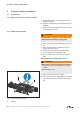
Maintenance and repair 7.2.3 Coupling The coupling sprocket (Fig. 12/k) is subject to wear and must be checked regularly (at least once a year). s5 CAUTION k n m q Fig. 12 Coupling k Coupling sprocket m Motor n Motor flange housing q Coupling half on the motor side s5 Screws Defective coupling sprocket Defective sprockets may lead to the rotor shaft breaking. To check the coupling switch the motor (Fig. 12/m) off and ensure that it cannot be switched on again. Undo the screws (Fig.
Maintenance and repair 7.3 Repair/ Service a) For on site repair work the motor must be disconnected from the mains by a qualified electrician so that it cannot be started up again accidentally. For repairs use the manufacturer, its branch offices or authorised dealers. Please contact the manufacturer for the address of the service centre responsible for you (see Manufacturer‘s address).
Maintenance and repair 7.4 Spare parts Order spare parts in accordance with the: • Spare parts list: E 832/1 ➝ S-VSI 100 (01) E 832/2 ➝ S-VSI 300 (01) E 832/3 ➝ S-VSI 300 (11) • Download the pdf file: http://www.gd-elmorietschle.com ➝ Downloads ➝ Product Documents ➝ S-Series ➝ Spare Parts • Parts subject to wear and gaskets are indicated separately on the list. • Web site: http://www.service-er.de • Select the type, size and design. NOTICE Fig. 14 Spare parts list (example) Fig.
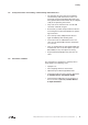
Malfunctions: Causes and elimination 8 Malfunctions: Causes and elimination Fault Cause Troubleshooting Important Machine is switched off by the motor protection switch Mains voltage/ Frequency does not correspond with the motor data Check by qualified electrician Section 5.
Malfunctions: Causes and elimination Fault Cause Troubleshooting Important Final pressure (max. vacuum) is not reached Machine or system leaking Check the pipework and screw connections for leaks and to ensure that they are firmly seated Section 7.2 Too little cooling water Note cooling water consumption Section 9 The mesh filter is dirty Clean or replace the mesh filter Section 7.2.2 Section 7.4 Ambient or intake temperature is too high Ensure it is being used properly Section 2.
Technical Data 9 Technical Data 100 S-VSI Sound pressure level (max.) 200 mbar (abs.) ➝ 0,1 mbar (abs.) EN ISO 3744 Tolerance ± 3 dB(A) Sound power level 300 (01) (01 (12) 50 Hz 72 74 74 60 Hz 75 78 76 50 Hz - 94 60 Hz - 97 dB(A) dB(A) Weight * kg 190 308 300 Length * mm 1082 1442 1323 Width mm 543 671 431 Height mm 404 442 562 G 11/2 G 2 1 /2 1.65 (1.0 ➝ H + 0.65 ➝ H1) 1.9 (1.1 ➝ H + 0.8 ➝ H1) 1.8 6.
www.gd-elmorietschle.com er.de@gardnerdenver.com Gardner Denver Schopfheim GmbH Roggenbachstraße 58 79650 Schopfheim · Deutschland Tel. +49 7622 392-0 Fax +49 7622 392-300 Elmo Rietschle is a brand of Gardner Denver‘s Industrial Products Division and part of Blower Operations.
EC - declaration of conformity 2006/42/EC Hereby the manufacturer confirms: Gardner Denver Schopfheim GmbH Postfach 1260 D-79642 Schopfheim that the machine: of the: Screw vacuum pump Series: S-VSI Type: S-VSI 100, S-VSI 300 is conform to the regulations of the guideline indicated above.
Safety declaration form for vacuum pumps and components 7.7025.003.17 Page 1 of 1 Gardner Denver Schopfheim GmbH Roggenbachstr. 58, 79650 Schopfheim Phone: +49/(0)7622/392-0 Fax: +49/(0)7622/392-300 Repairs and/or maintenance of vacuum pumps and components will only be carried out if a declaration has been filled in correctly and completely. If not, the repair work cannot be started and delays will result. This declaration must only be filled in and signed by authorised qualified staff. 1.