Instruction and service manual Screw vacuum pumps S-VSB S-VSB 120 S-VSB 200 S-VSB 320 S-VSB 430 S-VSB 800 S-VSB 2700 BE 831 2.1.2002 Gardner Denver Schopfheim GmbH Postfach 1260 79642 SCHOPFHEIM GERMANY Fon +49 7622 / 392 -0 Fax +49 7622 / 392 -300 e-mail: er.de@ gardnerdenver.com www.gd-elmorietschle.
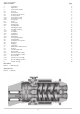
Screw vacuum pumps Table of contents: Page: 1. Introduction 3 2. Application 3 3. 3.1 3.2 3.3 3.4 3.4.1 3.4.2 3.4.3 3.5 3.5.1 3.5.2 3.6 General Construction General Construction Technical specifications Cooling system Fresh water cooling Circulation Cooling Cooling gas Gases Sealing gas Cleaning gas Bleeding valve 4 4 4 4 5 5 5 5 5 5 5 5 4. 4.1 4.1.1 4.1.2 4.1.3 4.2 4.2.1 4.2.2 4.3 4.4 4.5 4.6 4.
1. Introduction To prevent contamination from possible dangerous substances contained in the process, the exhaust outlet must always be connected to an appropriate emission control system. All units being returned to our works for maintenance or any other reason must be free of harmful and dangerous material. A Health and Safety certificate should always be provided.
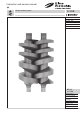
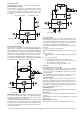
3. General Construction 3.1 General The Rietschle TWISTER pumps gases and vapours by use of two screw rotors, having a profile comprising a plurality of curves, i.e. Archimedean curve, Quimby curve and arc, which rotate smoothly with a certain clearance maintained between each other and inside wall of the casing. The gases and vapours being pumped are smoothly pressurised up to the pressure on the discharge side. The pump is so constructed as to prevent oil from entering the pumping chamber.
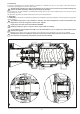
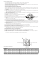
3.4 Cooling system TWISTER pumps are water cooled. They are distinguished in: 3.4.1 Fresh water cooling The fresh water cooling system is characterised by a continuous flow of the cooling water through a hollow space between the inner and outer wall of the chamber. For safety reasons the cooling system is equipped with a temperature switch and a flow switch. Cooling water inlet Cooling water outlet Flushing gas Cooling gas Flushing gas Cooling gas 3.4.
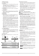
4. Handling procedure 4.1 Assembly of piping 4.1.1 Location • Mount the Pump on a clean, flat & level surface of sufficient rigidity. If it is to be installed outdoors, check motor, V-belt and other parts are for outdoor service. • There should be enough space for maintenance, disassembly, reassembly and periodical inspection, etc. 4.1.2 Foundation • The pump can be mounted on a suitable concrete plinth or steel framework. 4.1.
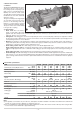
5. Maintenance and Inspection 5.1 General • During operation, the temperature will rise corresponding to the compression ratio due to compression heat. However, if localised temperature hot spots occur or the paintwork is scorched, this is abnormal. It may be because of the interference of rotor with casing, or the pump has sucked in some foreign material. Therefore, stop the pump immediately to check the condition.
5.3 Disassembly (see spare parts list E 831/1) 5.3.1 Cautions in disassembly (1) Put alignment marks on all connections and covers etc. (2) Take measurements of all gasket thickness when they are disassembled. (3) Keep disassembled parts away from dust, especially for bearings. 5.3.2 Disassembling procedure (1) Remove all accessories from the pump unit. (2) By opening drain valves, discharge cooling water from casing. (3) Remove oil drain plug from front end cover 4 and drain oil.
5.4.2 Re-assembly procedure (1) Insert plate guide (A) 8 & (B) 9 on front end plate 2 and secure with socket bolt (M8). (2) Insert plate guide (B) 9 on rear end plate 3 and secure with socket bolt. (M8). (3) Insert drive shaft (A) 6 & driven shaft (B) 7 on front & rear end plate. (4) The reassembly should be done from gear side (=discharge side) first. Insert mechanical seals on drive & driven shaft. (5) Inset spacer (A) 36 on drive & driven shaft.
6.
EC - declaration of conformity 2006/42/EC Hereby the manufacturer confirms: Gardner Denver Schopfheim GmbH Postfach 1260 D-79642 Schopfheim that the machine: of the: Screw vacuum pump TWISTER Series: S-VSB Type: S-VSB 120, S-VSB 200, S-VSB 320, S-VSB 430, S-VSB 800 is conform to the regulations of the guideline indicated above.
Safety declaration form for vacuum pumps and components 7.7025.003.17 Page 1 of 1 Gardner Denver Schopfheim GmbH Roggenbachstr. 58, 79650 Schopfheim Phone: +49/(0)7622/392-0 Fax: +49/(0)7622/392-300 Repairs and/or maintenance of vacuum pumps and components will only be carried out if a declaration has been filled in correctly and completely. If not, the repair work cannot be started and delays will result. This declaration must only be filled in and signed by authorised qualified staff. 1.