Directions for Use and Service Manual for compact units of Types from WPB 120 to WPB 8300, and of Types from WVB 120 to WVB 8300, and Base units of Types from WPB 120 to WPB 8300 BE 853 2.5.2004 Gardner Denver Schopfheim GmbH Postfach 1260 • 79642 SCHOPFHEIM / GERMANY Phone 07622/392-0 • Fax 07622/392300 er.de@gardnerdenver.com www.gd-elmorietschle.
TABLE OF CONTENTS 1. Basic information 1.2. Symbols used in the manual 2. 10. Transport and transport data 2.2. Handling 2.3. Storage conditions Pressure Device Non-standard blower drive Appendices 1. Identification of Characteristic Values, Standard compact unit Diagram, and pressure ratios of standard blower set Transport, Handling and Storage 2.1. 3. 9. Introduction 1.1. 2. 3.1 Installation and Assembly 3.
1. INTRODUCTION 1.1 BASIC INFORMATION 2. The Directions for use and service manual for the SHARK compact unit and base units (hereinafter referred to as the Manual) contain important directions to be observed throughout the machine’s operating life, starting on receipt of the machine. The manual has been compiled for complete SHARK series. It also applies to separately delivered base units.
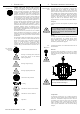
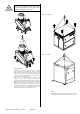
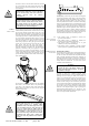
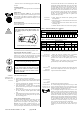
WARNING On no account should the compact unit be lifted with the ropes attached to the set bases, blower flanges, suction silencer, and/or motor! Without a compact unit With a compact unit Acoustic enclosure Smaller types of acoustic enclosures, in which compact units are placed, can be handled by a crane or a forklift truck. Ropes must be placed under the bottom base as displayed in the picture - in the direction shown by the arrows.
The blower set must be stored in its original packaging in a dry place and must be protected against dust. Compact units in the acoustic enclosure intended for outside use can be stored in the open air. If the blower set has been stored for more than six months, you should (re)preserve it. For this purpose, you can use standard preservative agents. Storage conditions: Temperature: -30 °C up to 40 °C Relative humidity: up to 80% 2.3 STORAGE CONDITIONS 3.
0,05 Vacuum version WVB: 1 2 4 3 F 4 F After the flanged connections have been tightened, the blower must spin smoothly! 4 Rules for connecting the pipeline: • The pipeline must be installed in the compensator axis. • The pipeline must be placed on both fixed and sliding points. It is not permissible to load the compensator with the pipeline weight. The first fixed point of the pipeline must be as near to the compensator as possible.
the electric motors in the star-delta connection (soft-start, etc.) even when the user could connect high-power electric motors directly (in the delta connection). The “soft” start saves the blower. WARNING Electric motors with power of over 11 kW must not be started directly (in the delta connection) without approval from the blower’s manufacturer. Before putting on the belts, you must remove the supports securing the pendulous motor frame in the lifted position.
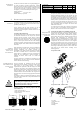
4. 4.1 BLOWER DESCRIPTION 4.2 BLOWER SET DESCRIPTION MACHINE • Optional accessories: The RT SHARK-compact units sets are fitted with RT base units of the Roots type with three-tooth rotors. a) A suction pressure gauge, or an electric indicator of filter clogging instead of the visual indicator. The Rietschle Thomas Roots blowers work on the principle of oil-free gas transport. These blowers are the most widespread type of two-rotor blowers. The axes of the rotor rotation are parallel.
4.5 USE 4.5.1 WORK MEDIA 4.5.2 SUCTION AND DISCHARGE TEMPERATURES 4.5.3 SUCTION AND DISCHARGE PRESSURES 4.5.4 LUBRICANT SPECIFICATION Blowers are used to transport and compress gases. Since the rotors neither touch each other nor are in contact with the casing, blowers are suitable for oil-free transport and gas compression. During transport, media are not contaminated with either abrasion particles or oil.
- Check all valves in the discharge pipeline whether they are open. You must turn the nut until it moves with difficulty, then turn the nut a further approximately 180°. The cone will be unloaded and the safety valve will start releasing air. Then you must tighten the nut again. Larger blower sets are equipped with safety valves with control valves.
While the maximum oil level is in the middle of the oil level gauge, the minimum level is 3 mm lower. The oil level measured when the machine is turned off must be maintained within these limits. When the oil level has reached the minimum, you must immediately top up with oil. Top up with oil carefully so that its level will not be above the middle of the oil level gauge. Otherwise, oil could leak through the release openings or into the blower when the machine is in operation.
- C 21 Suspension point 5.7 PLATES AND LABELS USED ON BASE UNITS AND COMPACT UNITS Plates and labels on base units and compact units: Base unit, compact unit and sound enclosure plate - Plate - warning - “ATTENTION“ red plate. On the suction silencer or the acoustic enclosure.
LIST OF POSSIBLE FAILURES AND METHODS FOR REMOVING THEM FAILURE POSSIBLE CAUSE REMOVAL The machine will not start Electrical part failure Check the wiring, contactors, fuses, thermal or other protection, and cable connection state. Check the state and functioning of the electric motor. Oil leaks through the ventilation openings High oil level (measured when the blower is turned off) Drain excessive oil.
might be a change in the resistance after the machine has been operated for some time. This is caused by pipeline clogging, clogging of the tanks’ aeration openings in wastewater treatment plants, etc., or by operators’ unfamiliarity (see Chapter 5.6). 5.9 ROUTINE MAINTENANCE Table 5 – Blower checks Operating time AND CHECKS After 400 hours Check Blower operation check. In a dry continental climate, preserve the rotors and cylinders after a six-week standstill.
• Blowers must not be operated when the suction part is open because the rotors are accessible. There is a risk of touching them. • Do not operate the machine if any of its guards is damaged (belt guards, fan guards, etc.). • Use protective gloves – the machine temperature is high when it is in operation or before it cools down. • Use ear protectors when the acoustic enclosure is open or the machine is operated without such a hood.
The necessity of such replacements is explained. The frequency of replacements depends on the ambient dustiness and the method of the blower set use. Type testing was executed by Brno-based Strojírenský zkušební ústav s.p. 2. Purchased from the GMBH HEROSE company; the conformity of these valves has been assessed in accordance with the European Parliament and Council’s Directive 97/23/ES. The products are marked with the CE 0045 symbol.
APPENDIX 1 IDENTIFICATION OF THE CHARACTERISTIC VALUES, STANDARD BLOWER SET DIAGRAM, AND PRESSURE RATIOS OF THE STANDARD BLOWER SET t0 1 ts 9 M Pm nm ps P n i V 20 5 10,14,15 3 tv 4 6 t3 VV pv 1 Suction filter and silencer 2 Blower 3 Discharge silencer 4 Non-return flap valve 5 Safety valve 6 Compensator 9 Electric motor 10,14,15 Belt drive 20 Starting valve 3,4,6 1m Lm p3-p0 pv p3 2 p0 1 ps 1 - Pressure loss of the suction filter and silencer 2 - Blower differential pressure 3,4,6 -
APPENDIX 2 PVO COMBINED SAFETY AND STARTING VALVE Rietschle Thomas GmbH + Co.
APPENDIX 3.1 FORCED VENTILATION, THE BLOWER SET IS IN THE ENCLOSURE, THE BLOWER SUCKS AIR FROM THE MACHINE HALL VVV+ VV VV VV + V V VVV+ VV + V V FORCED VENTILATION, THE BLOWER SUCKS AIR FROM THE MACHINE HALL VV V VV + V V F G L M N O Rietschle Thomas GmbH + Co.
APPENDIX 3.2 FORCED VENTILATION, THE BLOWER SUCKS AIR FROM THE OUTSIDE VV V VV V NATURAL VENTILATION, THE BLOWER SUCKS AIR FROM THE MACHINE HALL VV V VV + V V F L M N O P Rietschle Thomas GmbH + Co.
APPENDIX 4 CONNECTION DIAGRAM OF THE NOISE-DAMPING HOOD FAN (3×400V) Blower motor 3 ~ ≥ 11 kW (Y/D); Fan 3 ~ B B D Y F Y/D Y D F B - Blower drive F - Fan Blower Motor 3 ~ < 11 kW (D); Fan 3 ~ B B F B - Blower drive F - Fan Rietschle Thomas GmbH + Co.
APPENDIX 5 CONNECTION DIAGRAM OF THE ACOUSTIC ENCLOSURE FAN (1×230V) Blower Motor 3 ~ ≥ 11 kW (Y/D); Fan 1 ~ B B Y F Y/D Y D F D B - Blower drive F - Fan Blower Motor 3 ~ < 11 kW (D); Fan 1 ~ B B - Blower drive F - Fan Rietschle Thomas GmbH + Co.
APPENDIX 6 REPORT ON MEASUREMENT OF THE COMPACT UNIT OSCILLATION POWER The picture shows the measurement points for the blower and electric motor. It is necessary to respect the point marking for simplification of mutual communication. Vd2 Ad1 Vd3 Am6 Hd2 Hd3 Hd1 Hd4 Vd1 Vm6 Hm6 Hm5 Vm5 Vd4 Vibration Measurement Vibration values - total value / Frequency [Hz] - Vibration value Measurement point C.V. F V.F. F V.F. F V.F.