Edition: 04.2010 · 610.48060.40.
© 2010 Gardner Denver Deutschland GmbH · Industriestraße 26 · 97616 Bad Neustadt · Germany Replication, distribution and / or editing of this document and the use and distribution of its content is prohibited unless explicitly permitted. Violation obligates compensation for damages. All rights reserved in case of the issue of a patent, utility patent or design patent.
Contents Contents 1 Glossary ..............................................................................................................................................6 2 Safety ..................................................................................................................................................7 2.1 Definitions .................................................................................................................................7 2.1.1 Safety alert symbol.........
Contents 13 Accessories .......................................................................................................................................44 13.1 Flanges....................................................................................................................................44 13.2 Non-return valve......................................................................................................................44 13.3 Gas ejector.............................................
List of Illustrations List of Illustrations Fig. 1: Dimensions .............................................................................................................................13 Fig. 2: Minimum inlet pressure/cavitation limit ...................................................................................17 Fig. 3: Design and operation of liquid-ring vacuum pumps/compressors (cross-section of operating chamber) ...........................................................................
Glossary 1 Glossary In these instructions the following technical terms with the specified meaning are used: Designation: Definition: Vacuum pump Machine for generating a vacuum. Compressor Machine for generating a gauge pressure. Machine Here: Vacuum pump or compressor. Unit for extracting, transporting and compressing gases and/or vapors, as well as for generating vacuum and gauge pressure. Here the drive is not considered part of the machine.
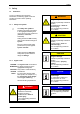
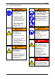
Safety 2 Safety 2.1 Definitions To point out dangers and important information, the following signal words and symbols are used in these operating instructions: 2.1.1 WARNING Danger of injuries. Indicates a potentially hazardous situation, that could result in death or serious injury if the corresponding measures are not taken.
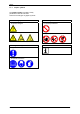
Safety 2.1.3 Graphic symbols The graphic symbol is located in safety precautions in the left-hand field. There are several types of graphic symbols: Hazard alerting symbols Prohibition symbols ... for general dangers: ... for general prohibitions: ... for special dangers: ... for special prohibitions: Mandatory action symbols Information ... for general instructions: ... for special instructions: 610.48060.40.
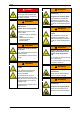
Safety 2.2 General safety precautions WARNING WARNING Improper use of the unit can result in serious or even fatal injuries! When working on the unit, there is a danger of injury, e.g.
Safety DANGER WARNING Electrical danger! Danger due to gauge pressure and vacuum! Do not open the motor terminal box unless absence of electricity has been ensured! Danger due to escaping fluid! Only operate the unit with the pipes/hoses connected to the intake and discharge connection, as well as to the operating-liquid port! WARNING Danger due to gauge pressure and vacuum! WARNING Danger due to escaping fluid! Before beginning work on the unit or system: Danger from rotating impeller of
Safety 2.3 WARNING Residual risks WARNING Danger of burns and scalding from hot surfaces of the pumpmotor unit and from hot fluids! Danger zone: Do not touch during operation! Allow to cool after shut-down! A Shaft exposed in gap between drive motor and vacuum pump/compressor.
Intended Use 3 Intended Use These operating instructions When operating the L-BV7, the limits listed in Chapter 4, "Technical Data", Pg. 13 ff. must always be complied with.
Technical Data 4 Technical Data 4.1 Mechanical data Dimensions A W S5 N1.0 W3 S4 H6 H1 P3 d H2 H4 W1 H3 P2 N3.0 N2.0 G N8.7 S2 B1 B L N4.2 R M E Fig. 1: Dimensions N1.0 N2.0 N3.0 N4.2 N8.7 Inlet connection Discharge connection Operating-liquid port Emptying or drain opening Connection for cavitation protection Specification in mm Type 2BV7 060 ...-1 ...-2 ...-3 A 335 372 B 162 B1 2BV7 061 2BV7 070 2BV7 071 ...-1 ...-2 ...-3 ...-1 ...-2 ...
Technical Data Specification in mm Type 2BV7 060 2BV7 061 2BV7 070 2BV7 071 ...-1 ...-2 ...-3 ...-1 ...-2 ...-3 68 89 89 99 96 99 218 218 235 235 300 261 300 161 180 180 201 202 265 225 265 R 59 55 55 71 71 81 78 81 S2 10 10 10 12 12 12 12 12 ...-1 ...-2 ...-3 M 72 68 P2 200 P3 S4 M25 x 1.5 M32 x 1.5 S5 M16 x 1.5 M32 x 1.
Technical Data Specifications in inches Type 2BV7 060 2BV7 061 2BV7 070 2BV7 071 ...-1 ...-2 ...-3 ...-1 ...-2 ...-3 8.58 9.25 9.25 11.8 10.3 11.8 7.09 7.09 7.91 7.95 10.4 8.86 10.4 2.32 2.17 2.17 2.80 2.80 3.19 3.07 3.19 0.394 0.394 0.394 0.472 0.472 0.472 0.472 0.472 ...-1 ...-2 ...-3 P2 7.87 8.58 P3 6.34 R S2 S4 M25 x 1.5 M32 x 1.5 S5 M16 x 1.5 M32 x 1.5 W 1.26 1.26 1.26 1.65 1.65 1.65 1.65 1.65 W1 4.33 4.33 4.33 4.72 4.72 4.72 4.72 4.
Technical Data 4.3 Weight Type Temperatures Weight [kg] [lbs] 2BV7 060-1A.0. approx. 16 approx. 35.3 2BV7 060-2A.0. 2BV7 060-3A.0. approx. 17 approx. 18 approx. 37.5 approx. 39.7 2BV7 061-1A.0. 2BV7 070-1A.0. approx. 22 approx. 31 approx. 48.5 approx. 68.3 2BV7 070-2A.0. 2BV7 070-3A.0. approx. 35 approx. 48 approx. 77.2 approx. 106 2BV7 071-1A.0. 2BV7 071-2A.0. approx. 39 approx. 50 approx. 86 approx. 110 2BV7 071-3A.0. approx. 56 approx.
Technical Data 300 4.5 250 4 200 p1 [psia] p 1 [mbar abs.] 3.5 150 3 2.5 2 1.5 100 1 0.5 50 0 0 0 0 20 40 60 50 100 150 200 f l [°F] 80 fl [°C] Fig. 2: Minimum inlet pressure/cavitation limit fl [°C, °F] p1 [mbar abs., psia] = Temperature of operating liquid = Inlet pressure abs. The minimum permissible inlet pressure of the pump-motor unit is dependent on the temperature of the operating liquid.
Description of Vacuum Pump/Compressor 5 Description of Vacuum Pump/Compressor Fig. 3: Design and operation of liquid-ring vacuum pumps/compressors (cross-section of operating chamber) 2 3 1 1 2 3 4 5 6 7 8 4 5 6 Discharge connection Operating-liquid port Inlet connection Impeller Housing Discharge port Inlet port Operating liquid 7 8 5.1 5.2 Design Operating method The L-BV7 2BV7s are liquid-ring vacuum pumps compressors.
Description of Vacuum Pump/Compressor 5.3 Here the following additional distinctions are made: Operating modes The pump-motor unit can function in several different operating modes. These differ in how the pump-motor unit is supplied with operating liquid: Non-automatic operation In this case the operating liquid feed is switched on and off manually with a stop valve. Self-priming operation See Fig. 11, Pg. 32. Operation with operating-liquid feed: – – 5.3.
Transport and Handling 6 Transport and Handling Manual handling: WARNING Danger from tipping or falling loads! WARNING Prior to transport and handling make sure that all components are securely assembled and secure or remove all components the fasteners of which have been loosened! Danger from lifting heavy loads! Manual handling of the unit is only permitted within the following limits: max. 30 kg [max. 66 lbs] for men max. 10 kg [max. 22 lbs] for women max. 5 kg [max.
Transport and Handling Transport and handling by means of a crane and strap belts is advisable. Attach the strap belts as shown in Fig. 4, Pg. 21: Use two strap belts, of which one is routed under the vacuum pump/compressor housing, and one under the fan guard. The strap belts should be seated securely in the undercuts so that the unit cannot slip out. The belts must be sufficiently long (spread angle smaller than 90°). Make sure that no damage is caused to any attached fittings.
Installation 7 7.1 Installation Installation CAUTION CAUTION Danger of damage to the pump-motor unit due to overheating! Danger of crushing from unit tipping over! In the unmounted state, the unit can easily tip due to its weight distribution! When installing the unit, make sure that heat dissipation and cooling are not obstructed. The minimum distances specified in Chapter 4.1, "Mechanical data", Section "Minimum distances for heat dissipation", Pg. 16 must be complied with.
Installation Bolt the feet of the unit to the supporting surface with suitable securing elements, as shown in Fig. 6, Pg. 23. service life of the unit, this value may not be exceeded. Generally, this value can be adhered to without a special foundation or a special base plate. The points on the unit for measuring the vibration speed are shown in Fig. 5, Pg. 23. Fig. 6: Securing elements for bolting feet to supporting surface Fig. 5: Points for measuring the vibration speed 2BV7 06: M = 4 x M8-6.
Installation 7.2 Electrical connection (motor) CAUTION The electrical connection must be carried out as follows: according to the applicable national and local laws and regulations, according to the applicable systemdependent prescriptions and requirements, according to the applicable regulations of the utility company. Incorrect connection of the motor can lead to serious damage to the unit! Observe the motor rating plate.
Installation 7.3 WARNING Connecting pipes/hoses (vacuum pump/compressor) Electrical danger! The terminal box must be free from foreign bodies, dirt, humidity. Terminal box cover and cable entries must be tightly closed so as to make them dustproof and waterproof. Check for tightness at regular intervals. For motor overload protection: Use motor circuit breakers. Set the motor circuit breakers to the nominal current specified on the rating plate. Fig.
Installation Fill with operating liquid: 7.3.1 When and how the pump-motor unit must be filled with operating liquid the first time is dependent on the operating mode: For self-priming operation: During installation. For operation with operating-liquid feed: After completing installation. The inlet connection (Fig. 7, Pg. 25, Item 3) is marked with an arrow pointing downward (↓). Connect the inlet pipe here. The pumped gases/vapors are sucked in via this.
Installation 7.3.4 Notes NOTICE For operating liquid with impurities: Install a filter, screen or separator in the supply line if necessary. NOTICE In case of operating liquid with a high lime content: Soften operating liquid OR Decalcify pump-motor unit regularly (see Chapter 11.1, "Maintenance", Pg. 36). NOTICE To prevent installation residues (e.g. welding spatter) from entering the unit, a start-up screen should be installed in the inlet pipe for the first 100 operating hours. 7.
Commissioning 8 Commissioning 8.1 WARNING Preparation and start-up CAUTION Danger due to gauge pressure and vacuum! If the pumped gases/vapors discharged on the pressure side are passed on, then it must be ensured that the maximum discharge pressure of 1.1 bar abs. [16.
Commissioning Check connections of the pipes/hoses for leaks. WARNING Danger due to gauge pressure and vacuum! Check direction of rotation: The direction of flow of the pumped gases/vapors is marked with arrows on the intake and discharge connection.
Commissioning 8.2 Self-priming operation See Fig. 8, Pg. 30. Here the following must be watched: Starting the pump-motor unit: The pump-motor unit must be pre-throttled on the inlet side. This means a vacuum of at least 900 mbar abs. [13.1 psia] must be present in the inlet pipe (Item B) at switchon. Switch on the unit. The operating liquid is sucked in.
Commissioning 8.3 Operation with operating-liquid feed See Fig. 9, Pg. 31; and Fig. 10, Pg. 31, as well as Fig. 11, Pg. 32 and Fig. 12, Pg. 32. Proceed as follows here: Method A: Method B: 1) Set pre-pressure of operating liquid (Fig. 9, Pg. 31): 1) Start up the unit: For non-automatic operation (Fig. 11, Pg. 32): Open the stop valve (Item 4) manually. The operating liquid is fed in. Switch on the unit. Set a pre-pressure pA in the feed pipe for the operating liquid (Item A) around approx.
Commissioning 2 3 4 5 6 1 Fig. 11: Operation with operating-liquid feed: Non-automatic operation 1 2 3 Pump-motor unit Flow meter Control valve 4 5 6 2 Stop valve Filter Feed pipe for operating liquid 3 4 5 6 1 4a Fig. 12: Operation with operating-liquid feed: Automatic operation 1 2 3 4 Pump-motor unit Flow meter Control valve Solenoid valve, connected to motor 4a Bypass with stop valve (for priming) 5 Filter 6 Feed pipe for operating liquid 4x 3x t= A 8x 7x t=2s B Fig.
Operation 9 Operation 9.1 WARNING Self-priming operation Follow the instructions contained in Chapter 8.2, "Self-priming operation", Pg. 30 for this operating mode. Danger due to gauge pressure and vacuum! Danger due to escaping fluid! Danger due to rotating parts! 9.2 The pump-motor unit may only be put into operation when the following conditions are met: Start-up For non-automatic operation (Fig. 11, Pg. 32): Fan guard and vacuum pump/compressor housing are mounted.
Shut-Down and Longer Standstills 10 Shut-Down and Longer Standstills 10.1 Draining 10.2 Preparing for longer standstill Before a longer standstill (from approx. 4 weeks) or when there is danger of frost, proceed as follows: DANGER Drain pump-motor unit as described in Chapter 10.1, "Draining", Pg. 34. Remove the pipe/hose from the intake or discharge connection. Pour ½ l [0.132 gal (US); 0.110 gal (UK)] of preservative (rust protection oil, e.g.
Shut-Down and Longer Standstills 10.3 Storage conditions DANGER This chapter applies in the following cases: Electrical danger! new pump-motor units, pump-motor unit that are already installed in a system and were prepared for a longer standstill, as described in Chapter 10.2, "Preparing for longer standstill", Pg. 34.
Servicing 11 Servicing DANGER WARNING Electrical danger! Danger of burns and scalding from hot surfaces of the pumpmotor unit and from hot fluids! Before beginning work on the unit or system, the following measures must be carried out: Do not touch during operation! Allow to cool after shut-down! Deenergize. Secure against being switched on again. Determine whether deenergized. Ground and short-circuit. Cover or block off adjacent energized parts.
Servicing Contamination/Problem Remedy Dirt collects in the motor cooling fins. Fine-grain dirt (e.g. sand) get into the vacuum pump/compressor with the operating liquid or pumped gases/vapors. Install a liquid separator, filter or screen in the feed pipe. Impeller is jammed. OR Regularly dismantle and clean the vacuum pump/compressor housing as follows: Shut unit down. Drain the pump-motor unit as described in Chapter 10.1, "Draining", Pg. 34.
Servicing Contamination/Problem Remedy Dirt gets into the air passages (fan guard, external fan, cooling fins) of the motor. Clean the motor air passages regularly. To do so, proceed as follows: Carry out protective measures for the use of compressed air: Wear personal protective equipment (protective gloves and safety goggles), secure surroundings. Remove objects lying around. Blow in compressed air through the fan guard grate. It is prohibited to remove the fan guard! 1 2 Fig.
Servicing 11.2 Repairs/troubleshooting Fault Cause Remedy Carried out by Motor does not start, no motor noise. At least two power supply leads interrupted. Check fuses, terminals and cables for open circuit. Eliminate open circuit. Electrician Motor does not start, humming noise.. One power supply lead interrupted. Check fuses, terminals and cables for open circuit. Eliminate open circuit. Electrician Impeller is jammed. Free shaft by turning. See Chapter 11.1, "Maintenance", Pg. 36.
Servicing Fault Cause Remedy Carried out by Unit generates insufficient vacuum. Unit too small. Use larger unit. Operator Operating-liquid flow too low. Increase operating-liquid flow rate to up to 2x the nominal flow rate. See Chapter 8.2, "Self-priming operation", Pg. 30 or Chapter 8.3, "Operation with operating-liquid feed", Pg. 31. Operator Operating liquid too warm (nominal temperature: 15°C [59 °F]). Cool or increase operating-liquid flow, See Chapter 8.2, "Self-priming operation", Pg.
Servicing 11.3 Spare parts 11.3.1 Ordering nash_elmo spare parts When ordering nash_elmo spare parts, always indicate the following: Type designation ("2BV...", "2BH..." or "2BL..."), complete with all additions (as per rating plate) Serial number ("No E"), 13-digit (as per rating plate) Part item number, 4-digit (as per parts list for exploded view, Chapter 14, "Exploded View with Parts List", Pg.
Servicing 11.
Disposal 12 Disposal Have the entire pump-motor unit scrapped by a suitable disposal company. No special measures are required when doing so. For additional information on disposing of the unit, ask service. © Gardner Denver Deutschland GmbH 43 / 64 610.48060.40.
Accessories 13 Accessories 13.1 Flanges 13.2 Non-return valve The pipes on the intake and discharge side are connected to intake and discharge connections via the flanges. The non-return valve is basically a valve with a plate seat. Its function is to prevent the pumped gases/vapors as well as the operating liquid from flowing back out of the pump in case the operation of the pump-motor unit is interrupted. It is mounted on the inlet connection of the unit for this purpose. See Fig. 17, Pg. 44.
Accessories 13.3 Gas ejector Mounting The gas ejector is used when an inlet pressure of the unit in the range from 40 mbar [0.580 psi] to 10 mbar [0.145 psi] is to be achieved. The gas ejector compresses the pumped gases/vapors sucked in to the inlet pressure of the pump-motor unit. Ambient air at 20°C [68 °F] and 1013 mbar [14.7 psi] is used as a propellant. This air may not contain any liquid droplets. The gas ejector is mounted when connecting the pipes/hoses, as described in Chapter 7.
Accessories 3) Screw the hose nipple into the hole provided on the pump-motor unit. Use commercially available liquid sealant (e.g. Loctite) when doing so. Operating-liquid port: Angled hose nipple, directed toward the front. Connection for cavitation protection: Angled hose nipple, directed upward. Operation with a liquid separator and operating water return is the operating mode recommended for the pump-motor unit.
Accessories 1 2 3 4 Fig. 20: Mounting liquid separator, Part 1 of 2 © Gardner Denver Deutschland GmbH 47 / 64 610.48060.40.
Accessories 5 6 7 8 Fig. 21: Mounting liquid separator, Part 2 of 2 610.48060.40.
Accessories 13.5 Cavitation protection Cavitation is understood to be the production and sudden implosion of gas bubbles in the liquid being fed. If the pressure in the vacuum pump/compressor drops below the evaporation pressure of the liquid (on the intake side or in constricted areas), gas bubbles form.
Exploded View with Parts List 14 Exploded View with Parts List 14.1 Parts list Part Item No. Part Designation Part Item No. Part Designation Part Item No.
Exploded View with Parts List 14.2 Exploded view 079 027 080 A 072 035 037 007 058 033 053 051 026 049 069 025 045 036 127 068 050 047 125 002 6104806001001 Fig. 22: Exploded view: vacuum pump/compressor section (Example, delivered version may differ in some details) © Gardner Denver Deutschland GmbH 51 / 64 610.48060.40.
Exploded View with Parts List 682 680 681 651 650 042 642 640 690 641 691 503 663 500 662 501 661 095 451 452 450 455 * 467 008 005 006 001 A Fig. 23: Exploded view: motor section (Example, delivered version may differ in some details) * NOTE: Only with 2BV7 061. 610.48060.40.
Exploded View with Parts List Fig. 24: Exploded view: motor section (Example, delivered version may differ in some details) * NOTE: Only with 2BV7 070 and 2BV7 071. © Gardner Denver Deutschland GmbH 53 / 64 610.48060.40.
EU declaration of conformity EU declaration of conformity EU declaration of conformity Manufacturer: Gardner Denver Deutschland GmbH P.O. Box 1510 D-97605 Bad Neustadt / Saale Responsible for documentation: Holger Krause P.O.
Form for statement on safety Form for statement on safety Statement on health safety and on the protection of the environment For the safety of our employees and to comply with statutory requirements on handling substances harmful to the health and the environment, this statement must be enclosed, fully completed, with each unit/system sent.
Index Index Definitions ....................................................... 7 A Design........................................................... 18 Dimensions ................................................... 13 Accessories .............................................27, 44 Cavitation protection.................................49 Flanges.....................................................44 Gas ejector ...............................................45 Liquid separator...........................
Index Feed............................................. 19, 31, 33 Filling amount: ......................................... 17 Impurities ................................................. 27 Operating liquid with high lime content.... 27 Priming............................................... 26, 28 Regenerative operation ............... 19, 30, 33 Operating method ......................................... 18 I Information.......................................................8 Injuries ...................
Index Lime deposits ...........................................39 Other deposits ..........................................39 Required space .............................................22 Standstill, longer ........................................... 34 Residual risks ................................................11 T Storage conditions ........................................ 35 Running dry ...................................................25 Technical data........................................
© Gardner Denver Deutschland GmbH 59 / 64 610.48060.40.
610.48060.40.
© Gardner Denver Deutschland GmbH 61 / 64 610.48060.40.
610.48060.40.
© Gardner Denver Deutschland GmbH 63 / 64 610.48060.40.
www.gd-elmorietschle.de er.de@gardnerdenver.com Gardner Denver Schopfheim GmbH Roggenbachstraße 58 79650 Schopfheim · Deutschland Tel. +49 7622 392-0 Fax +49 7622 392-300 Elmo Rietschle is a brand of Gardner Denver‘s Industrial Products Group and part of Blower Operations. Gardner Denver Deutschland GmbH Industriestraße 26 97616 Bad Neustadt · Deutschland Tel.