Edition: 12.2009 · 610.444430.40.
Contents Contents 1 Safety ..................................................................................................................................................3 1.1 Definitions .................................................................................................................................3 1.1.1 Safety alert symbol.......................................................................................................3 1.1.2 Signal words.........................................
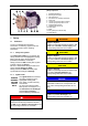
Safety Fig. 1: Design of liquid-ring vacuum pump/compressor 1 2 3 4 5 6 7 8 9 10 11 12 13 1 Safety 1.1 WARNING Definitions Danger of injuries. Indicates a potentially hazardous situation, that could result in death or serious injury if the corresponding measures are not taken. To point out dangers and important information, the following signal words and symbols are used in these operating instructions: 1.1.
Safety 1.2 General safety precautions DANGER WARNING Electrical danger! Before beginning work on the unit or system, the following measures must be carried out: Deenergize. Secure against being switched on again. Determine whether deenergized. Ground and short-circuit. Cover or block off adjacent energized parts.
Safety WARNING CAUTION Danger from rotating external fan of unit! Only operate the unit with the fan guard mounted! It is prohibited to remove the fan guard! Danger of crushing from unit tipping over! Secure the pump-motor unit on the installation surface before putting into operation! WARNING 1.
Intended Use 2 When operating the L-BV3, the limits listed in Chapter 3, "Technical Data", Pg. 7 ff. must always be complied with. If the L-BV3 is used to extract hot fluids, the necessary safety measures must be taken by the user.
Technical Data 3 Tightening torques Technical Data 3.1 The values specified here for tightening torques apply unless other values are indicated. Mechanical data Weight Type Tightening torques for screw connections (pipe-connections) Weight approx. approx. [kg] [lbs] 2BV3151 9 19.8 Higher weights are possible with special models. Thread [Nm] ± 10 % [ft lbs] ± 10 % G⅛ 4.5 3.32 G⅜ 16 11.
Technical Data Operating-liquid temperature: max. +40 °C min. +5 °C Nominal value: +15 °C Max. permissible pressure in the pumpmotor unit pint max during compressor operation: max. +104 °F min. +41 °F 300 kPa abs. 43.5 psia If higher pressures can occur in the system, then corresponding protective devices must be provided. +59 °F Ambient temperature: max. +40 °C min. +5 °C Max. pre-pressure of the operating liquid 300 kPa abs. 43.
Operating modes 4 Operating modes NOTICE The pump-motor unit can function in several different operating modes. These differ in how the pump-motor unit is supplied with operating liquid: The following is dependent on the operating mode: when and how the pump-motor unit must be filled with operating liquid the first time, how the pump-motor unit is put into operation. The specifications for this are contained in Chapter 6, "Installation", Pg. 11ff., and Chapter 7, "Commissioning", Pg. 16ff.
Transport and Handling 5 Transport and Handling WARNING WARNING Danger from tipping or falling loads! Do not hold the pump-motor unit on the capacitors or cable glands on the terminal box! Improper use of the machine can result in serious or even fatal injuries! Have you read the safety precautions in Chapter 1, "Safety", Pg. 3 f.
Installation 6 Installation CAUTION Danger of damage to the pump-motor unit due to overheating! When installing the unit, make sure that heat dissipation and cooling are not obstructed. The minimum distances specified in Chapter 3.1, "Mechanical data", Section "Minimum distances for heat dissipation", Pg. 7 must be complied with.
Installation service life of the pump-motor unit, this value may not be exceeded. Generally, this value can be adhered to without a special foundation or a special base plate. The points on the unit for measuring the vibration speed are shown in Fig. 2, Pg. 12. DANGER Electrical danger! Before beginning work on the unit or system, the following measures must be carried out: Deenergize. Secure against being switched on again. Determine whether deenergized. Ground and short-circuit.
Installation All conductors under outer angled grounding brackets must be bent into a "U" shape. Regulations: The electrical connection must be carried out as follows: according to the applicable national and local laws and regulations, This also applies to: the protective conductor, according to the applicable systemdependent prescriptions and requirements, the outer ground conductor. according to the applicable regulations of the utility company.
Installation 6.3 Connecting pipes/hoses (vacuum pump/compressor) CAUTION To prevent foreign bodies from entering the unit, all connections are sealed off when delivered. Do not remove the sealing plugs until immediately before connecting the pipes/hoses. If the unit is run dry, the mechanical seal will be destroyed in a matter of seconds! DO NOT switch on as long as the unit is not filled with operating liquid! Fill with operating liquid: For the arrangement of the pipe/hose connections, see Fig.
Installation 6.3.3 NOTICE NOTICE Attach pipes/hoses free of mechanical tensions. Support the weight of the pipes/hoses. 6.3.1 Notes For operating liquid with impurities: Install a filter, screen or separator in the supply line if necessary. Inlet connection and discharge connection NOTICE The inlet connection (Fig. 3, Item 3) is marked with an arrow pointing downward (↓). Connect the inlet pipe here. The pumped gases/vapors are sucked in via this.
Commissioning 7 Fill with operating liquid: Commissioning For operation with self-priming of the operating liquid during installation (see Chapter 6.3, "Connecting pipes/hoses (vacuum pump/compressor)", Pg. 14). WARNING Improper use of the machine can result in serious or even fatal injuries! Have you read the safety precautions in Chapter 1, "Safety", Pg. 3 f.
Commissioning 7.2 DANGER Self-priming operation CAUTION Electrical danger! The electrical connection may be carried out by trained and authorized electricians only! The liquid level in the feed pipe or in the reservoir may not exceed the height of the shaft center of the pump-motor unit! If this height is exceeded, too much liquid gets into the pump-motor unit.
Commissioning 7.3 For automatic operation (Fig. 7, Pg. 19): Operation with operating-liquid feed Switch on the unit. See Fig. 5, Pg. 18, and Fig. 8, Pg. 19, as well as Fig. 6, Pg. 19, and Fig. 7, Pg. 19. The solenoid valve (Item 4) opens and the operating liquid is fed in. Proceed as follows here: Method A: 1) Set pre-pressure of operating liquid (Fig. 5, Pg. 18): Method B: Set a pre-pressure pA in the feed pipe for the operating liquid (Item A) around approx. 100 kPa [14.
Commissioning 2 1 3 4 5 2 6 1 6104443001008 4 3 5 6 4a 6104443001009 Fig. 6: Operation with operating-liquid feed: Non-automatic operation Fig.
Operation 8 Operation CAUTION The feeding in of overheated steam at the inlet connection of the pump-motor unit while it is not rotating has the following effect: Operating liquid is pressed out of the pumpmotor unit. Considerable thermal loading of the pumpmotor unit. The pump-motor unit may be damaged! Before feeding in overheated steam at the inlet connection, switch on the pump-motor unit for approx. 10 s to ensure sufficient supply with operating liquid.
Operation For automatic operation (Fig. 7, Pg. 19): Switch off the pump-motor unit. The solenoid valve (Item 4) closes, and feeding of the operating liquid is cut off. The following applies for the control valve (Item 3) for setting the operating-liquid flow rate: In case of an interruption in operation, the valve setting (i.e. the valve position or the open valve cross-section) is not changed. © Gardner Denver Deutschland GmbH 21 / 32 610.444430.40.
Shut-Down and Longer Standstills 9 Disconnect the hose connections on the inlet connection, discharge connection and operating liquid opening. Shut-Down and Longer Standstills Remov ethe mounting screws on the feet of the pump-motor unit. WARNING Improper use of the machine can result in serious or even fatal injuries! Have you read the safety precautions in Chapter 1, "Safety", Pg. 3 f.
Shut-Down and Longer Standstills described in Chapter 7, "Commissioning", Pg. 16. For pump-motor unit that are already installed in a system: Commission the pump-motor unit as described in Chapter 7, "Commissioning", Pg. 16. DANGER Electrical danger! Work on electrical installations may be carried out by trained and authorized electricians only! 6104443001004 Fig. 10: Pour in preservative and turn shaft 9.
Servicing 10 Servicing WARNING WARNING Danger due to gauge pressure and vacuum! Danger due to escaping fluid! Before beginning work on the unit or system: Interrupt supply of operating liquid. Bleed lines and vacuum pump/compressor (depressurize). Improper use of the machine can result in serious or even fatal injuries! Have you read the safety precautions in Chapter 1, "Safety", Pg. 3 f.
Servicing Contamination/Problem Remedy Dirt collects in the motor cooling fins. Clean the motor cooling fins at regular intervals. Fine-grain dirt (e.g. sand) get into the vacuum pump/compressor with the operating liquid or pumped gases/vapors. Install a liquid separator, filter or screen in the feed pipe. Impeller is jammed. It is prohibited to remov ethe vacuum pump/compressor housing! Free shaft by turning. To do so, proceed as follows: Shut unit down.
Servicing 6104443001004 Fig. 11: Pouring in decalcifying agent and freeing shaft by turning 10.2 Repairs/troubleshooting Fault Cause Remedy Carried out by Motor does not start, no running noise. Interruption of the power supply, with single-phase model in one cable, with twophase model in at least two cables. Check fuses, terminals and cables for open circuit. Eliminate open circuit. Electrician Motor does not start, humming noises. One power supply lead interrupted.
Servicing Fault Cause Remedy Carried out by Protective motor switch trips when motor is switched on. Winding shortcircuit. Have winding checked. Electrician Motor overloaded. Check operating-liquid flow rate and reduce if necessary. See Chapter 7.2, "Self-priming operation", Pg. 17 or 7.3, "Operation with operating-liquid feed", Pg. 18. Operator Counter-pressure at discharge connection too high. Reduce counter-pressure. Operator Share of liquid also fed too high.
Servicing Fault Unit leaky. Cause Remedy Carried out by Operating-liquid flow rate too high. Check operating-liquid flow rate and reduce if necessary. See Chapter 7.3, "Operation with operating-liquid feed", Pg. 18. Operator Pump-motor unit is started while flooded. Check operating-liquid flow rate and reduce if necessary. After switching off pump-motor unit, no operating liquid may be fed in. See Chapter 7.3,“Operation with operating-liquid feed“, Pg. 18. Operator Seals defective. Check seals.
Disposal A so-called Declaration of Clearance must be included with each pump-motor unit that is given to a workshop for inspection, maintenance or repair. 10.3 Service/After-sales service Our Service is available for work (in particular the installation of spare parts, as well as maintenance and repair work), not described in these operating instructions (see front page of these operating instructions).
EC Declaration of Conformity EC Declaration of Conformity EU declaration of conformity Manufacturer: Gardner Denver Deutschland GmbH P.O. Box 1510 D-97605 Bad Neustadt / Saale Responsible for documentation: Holger Krause P.O.
Form for statement on safety Form for statement on safety Statement on health safety and on the protection of the environment For the safety of our employees and to comply with statutory requirements on handling substances harmful to the health and the environment, this statement must be enclosed, fully completed, with each unit/system sent.
www.gd-elmorietschle.de er.de@gardnerdenver.com Gardner Denver Schopfheim GmbH Roggenbachstraße 58 79650 Schopfheim · Deutschland Tel. +49 7622 392-0 Fax +49 7622 392-300 Elmo Rietschle is a brand of Gardner Denver‘s Industrial Products Group and part of Blower Operations. Gardner Denver Deutschland GmbH Industriestraße 26 97616 Bad Neustadt · Deutschland Tel.