Edition: 09.2011 · 610.44434.40.
Contents Contents 1 Safety ..................................................................................................................................................3 1.1 Definitions .................................................................................................................................3 1.1.1 Safety alert symbol.......................................................................................................3 1.1.2 Signal words.........................................
Safety 1 Safety 1.1 CAUTION Danger of damage. Indicates a potentially hazardous situation that may result in property damage if the corresponding measures are not taken. Definitions To point out dangers and important information, the following signal words and symbols are used in these operating instructions: 1.1.1 NOTICE Safety alert symbol The safety alert symbol is located in the safety precautions in the highlighted heading field on the left next to the signal word (DANGER, WARNING, CAUTION).
Safety WARNING When working on the unit, there is a danger of injury, e.g.
Safety WARNING Danger from rotating impeller: Cutting/cutting of off extremities! The rotating impeller is accessible with the inlet and discharge connections open! Do not reach into the unit through open connections! Do not insert objects into the unit through the openings! WARNING Danger zone: Fan guard Hazard: Long, loose hair can be drawn into external fan through fan guard grate, even with fan guard mounted! Protective measures: Wear hair net! WARNING Danger from rotating impeller: Cutting/cut
Intended Use 2 are intended for industrial applications, Intended Use are designed for continuous operation. With increased switch-on frequency (6x per hour with equal pauses and operating times) or with increased gas inflow and ambient temperature, the excess temperature limit of the coil and the bearing can be exceeded. Consult the manufacturer when using under such conditions. When operating the G-BH1, G-BH9 the limits listed in Chapter 3, "Technical Data", Pg. 7 ff. must always be complied with.
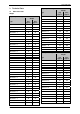
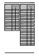
Technical Data 3 Technical Data 3.1 Single-impeller design Weight Mechanical data Type Weight Single-impeller design Weight Type [kg] approx. [lbs] approx. 2BH1100-7..0. 9 20 2BH1200-7..0. 9 20 2BH1300-7..0. 9 20 2BH1300-7..1. 10 22 2BH1300-7..2. 11 24 2BH1330-7..0. 10 22 2BH1330-7..1. 11 24 2BH1330-7..2. 12 26 2BH1400-7..0. 13 29 2BH1400-7..1. 16 35 2BH1400-7..2. 17 37 2BH1430-7..0. 14 31 2BH1430-7..1. 17 37 2BH1430-7..2. 18 40 2BH1500-7..0.
Technical Data Noise level Two-impeller design Weight Type [kg] approx. [lbs] approx. 2BH181.-7..3. 203 448 2BH181.-7..4. 215 474 2BH184.-7..2. 177 390 2BH184.-7..3. 203 448 2BH191.-7..1. 274 604 2BH191.-7..2. 288 635 2BH191.-7..3. 299 659 2BH191.-7..4. 309 681 2BH1940-7B.2. 275 606 2BH1940-7B.3. 314 692 2BH1940-7B.4. 324 714 2BH1943-7..2. 330 728 2BH1943-7..3. 339 747 2BH1943-7..4.
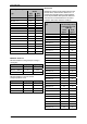
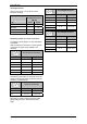
Technical Data Single-impeller design Type Two-impeller design 1-m measuring-surface sound pressure level L [dB (A)] 50 Hz approx. 60 Hz approx. 2BH1630-7..1. 69 72 2BH1630-7..2. 69 2BH1630-7..3. Type 1-m measuring-surface sound pressure level L [dB (A)] 50 Hz approx. 60 Hz approx. 2BH1310-7..2. 55 61 72 2BH1410-7..3. 66 69 69 72 2BH1410-7..4. 66 69 2BH1630-7..6. 69 72 2BH1510-7..4. 72 74 2BH1630-7..7. 69 72 2BH1510-7..5. 72 74 2BH180.-7..0. 70 74 2BH1610-7..1.
Technical Data Sound power level Tightening torques for metal threaded glands/unions Sound power level LW as per EN ISO 3744, tolerance 3 dB (A). Two-impeller design Sound power level LW [dB (A)] Thread [Nm] [ft lbs] M12x1,5 4-6 2.95 - 4.43 M16x1,5 5 - 7.5 3.69 - 5.53 50 Hz 60 Hz M25x1,5 6-9 4.43 - 6.64 2BH191. - 98 M32x1,5 2BH1940 - 98 M40x1,5 8 - 12 5.9 - 8.85 2BH1943 - 99 2BH923..
Technical Data 3.2 Installation altitude Electrical data Max. of 1,000 m [3,280 ft] above sea level. When installing the pump-motor unit at an altitude of more than 1,000 m [3,280 ft] above sea level, first inquire with the Service department. See rating plate. 3.3 Operating conditions Temperatures Temperature of pumped gases: max. permissible temperature: +40°C [+104°F] Nominal value: +15°C [+59°F] Pump-motor units for higher fluid temperatures on request. Ambient max.
Transport and Handling 4 The transport must be carried out in different ways depending on the type: Transport and Handling 2BH11., 2BH12., 2BH13., 2BH14., 2BH15. (single-impeller): Manual handling WARNING Tipping or falling can lead to crushing, broken bones etc.! Sharp edges can cause cuts! Wear personal safety equipment (gloves, safety shoes and protective helmet) during transport! 2BH15. (two-impeller), 2BH16., 2BH18., 2BH19.
Installation 5 Installation WARNING WARNING Improper use of the unit can result in serious or even fatal injuries! Have you read the safety precautions in Chapter 1, "Safety", Pg. 3 f.
Installation Carry out the following work to install the pumpmotor unit: Minimum distances: Installation and securing, Attachment of the included loose muffler if necessary, Attachment of threaded flange or hose flange (available as accessories) for the connection of inlet or discharge pipe to the muffler, Electrical connection, Connection of inlet and discharge connection to the system.
Installation Sound protection hood (available as an accessory for the 2BH1): Noise protection hoods are suitable for installation in rooms and in the open. They reduce both the total sound pressure level and tonal components that are perceived as particularly annoying. Vertical axis mounting on the wall with the compressor cover pointing downward For vertical axis mounting of the unit on the wall, the unit is fastened using the holes in the foot. The foot of the unit has fastening holes.
Installation The electrical connection must be carried out as follows: Electrical power supply: Observe the rating plate. It is imperative that the operating conditions correspond to the data given on the rating plate! Deviations permissible without reduction in performance: The electrical connection must be permanently safe. There may be no protruding wire ends. Clearance between bare live parts and between bare live parts and ground: ≥ 5.5 mm [0.217"] (at a nominal voltage of UN ≤ 690V).
Installation For motor overload protection: Use motor circuit breakers. This must be adjusted to the specified nominal current (see rating plate). DANGER Electrical danger! There is danger of an electrical shock when a defective pump-motor unit is touched! Mount motor circuit breaker. Have electrical equipment checked regularly by an electrician. Interference immunity of drive motor: For drive motors with integrated sensors, the operator must provide for a sufficient interference immunity itself.
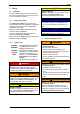
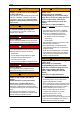
Installation 5.3 Connecting pipes/hoses (vacuum pump/compressor) Mufflers: The pump-motor units are delivered with mufflers (indicated with arrows in the following illustrations) for the inlet and discharge connections as standard equipment. On delivery the mufflers are already mounted on the following pump-motor units. Fig. 6: 2BH1840-7L... (two-impeller pump-motor unit with double-flow design) Fig. 2: 2BH1… (single-impeller pump-motor units), 2BH9 23 Fig.
Installation WARNING WARNING Danger from rotating impeller: Cutting/cutting of off extremities! The rotating impeller is accessible with the inlet and discharge connections open! With free entry and exit of gases, i.e.
Installation 5.3.3 Procedure when connecting pipes/hoses Attach the pipes/hoses to the unit as described in the following. The pipes/hoses are connected differently to inlet and discharge connections depending on the muffler design and the type of line (pipe or hose): Muffler with inside threads: The pipe is screwed directly into the muffler. Muffler without inside thread: – Screw threaded flange (available as an accessory) onto the muffler. – Screw the pipe into the threaded flange.
Commissioning 6 Commissioning WARNING Improper use of the unit can result in serious or even fatal injuries! Have you read the safety precautions in Chapter 1, "Safety", Pg. 3 f.
Commissioning 6.2 WARNING Start-up and shut-down Start-up Danger due to rotating parts! Danger due to vacuum and gauge pressure! Danger due to escaping fluid! Test runs may also only be conducted with the pump-motor unit completely mounted. Open shut-off device in intake/discharge pipe. Switch on power supply for drive motor. Shut-down: Switch off power supply for drive motor. DANGER Close shut-off device in intake/discharge pipe.
Operation 7 Operation CAUTION WARNING Improper use of the unit can result in serious or even fatal injuries! Have you read the safety precautions in Chapter 1, "Safety", Pg. 3 f.? Otherwise you many not carry out any work with or on the pump-motor unit! Also be sure to read the safety precautions in Chapter 6, "Commissioning", Pg. 21! Danger of bearing damage! Heavy mechanical impacts must be avoided during operating and while at a standstill.
Shut-Down and Longer Standstills 8 8.1 Shut-Down and Longer Standstills Preparing for shut-down or longer standstill WARNING Improper use of the unit can result in serious or even fatal injuries! Have you read the safety precautions in Chapter 1, "Safety", Pg. 3 f.
Servicing 9 9.1 Servicing Emptying/Rinsing/Cleaning Before any maintenance/servicing work, empty, rinse and clean the outside of the unit. WARNING Improper use of the unit can result in serious or even fatal injuries! Have you read the safety precautions in Chapter 1, "Safety", Pg. 3 f.? Otherwise you many not carry out any work with or on the pump-motor unit! Empty unit with air and rinse until all residues have been removed. Clean the outside of the unit with compressed air.
Servicing Fault Cause Remedy Carried out by Pump-motor unit does not generate any or generates insufficient pressure difference. Leak in system. Seal leak in the system. Operator Wrong direction of rotation. Reverse direction of rotation by interchanging two connecting leads. Electrician Incorrect frequency (on pump-motor units with frequency converter). Correct frequency. Electrician Shaft seal defective. Replace shaft seal. Service*) Different density of pumped gas.
Disposal 9.3 Service/After-sales service 10 Disposal Our Service is available for work (in particular the installation of spare parts, as well as maintenance and repair work), not described in these operating instruction. A list of spare parts with an exploded drawing is available on the Internet at www.gd-elmorietschle.com. Have the entire pump-motor unit scrapped by a suitable disposal company. No special measures are required when doing so.
EU declaration of conformity EU declaration of conformity EU declaration of conformity Gardner Denver Deutschland GmbH Industriestraße 26 97616 Bad Neustadt Germany Responsible for Holger Krause documentation: Industriestraße 26 97616 Bad Neustadt Germany Designation: G series Side channel blower G-BH1, G-BH9 Types 2BH1 1 2BH1 2 2BH1 3 2BH1 4 2BH1 5 2BH1 6 2BH1 8 2BH1 9 2BH9 23 The side channel blower described above meets the following applicable Community harmonisation legislation: 2004/108/EC*) Directiv
Statement on health safety and on the protection of the environment Statement on health safety and on the protection of the environment Statement on health safety and on the protection of the environment For the safety of our employees and to comply with statutory requirements on handling substances harmful to the health and the environment, this statement must be enclosed, fully completed, with each unit/system sent.
610.44434.40.
© Gardner Denver Deutschland GmbH 31 / 32 610.44434.40.
www.gd-elmorietschle.de er.de@gardnerdenver.com Gardner Denver Schopfheim GmbH Roggenbachstraße 58 79650 Schopfheim · Deutschland Tel. +49 7622 392-0 Fax +49 7622 392-300 Elmo Rietschle is a brand of Gardner Denver‘s Industrial Products Group and part of Blower Operations. Gardner Denver Deutschland GmbH Industriestraße 26 97616 Bad Neustadt · Deutschland Tel.