
Owner manual

610.44520.40.000 36 / 52 © Gardner Denver Deutschland GmbH
Commissioning
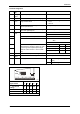
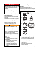
Display elements and function keys
z
y
wx
v
t
u
s
88888
8888
888
8
abcde
j gfkih PS
mno
p
qr
Hi
Hz
%sh
rpm
°C
Ω
m
AV
Lo
6
0
3
1
2
4
5
n_e2fcx002
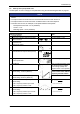
Fig. 25: Display elements and function keys
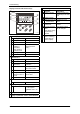
Status displays
Meaning Explanation
Ready
Pulse inhibit active Power outputs inhibited
Adjusted current
limitation is
exceeded in
motor−mode or
generator mode
C0022 (motor mode) or
C0023 (generator
mode)
Warning active
Fault active
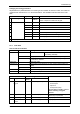
Function bar 1
Meaning Explanation
Without function Display = loc
Display of first code
in the menu
Active after every mains
connection
Code selection Four−digit display of the
active code number
Without function Is skipped
Change of
parameter value of
a code
Five−digit display of the
current value
Without function
Function bar 2
Not active
Bar graph display
Controller load Display range: −180 %
... +180 % (each
graduation mark = 20
%)
Display of code number
Display of parameter value or fault indication
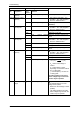
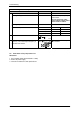
Function keys
Function Explanation
Enable controller Terminal X3/28 must
additionally be at HIGH
level
Inhibit controller
Change function bar
1 function bar 2
Function bar 2 not
active
To right/left in active
function bar
The active function is
framed
Increase/decrease
value
Fast change: Keep
respective key
pressed
Only blinking values
can be changed
Store parameters
when ! is blinking
Confirmation by
Store in display