
Owner manual
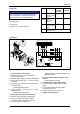

610.44520.40.000 28 / 52 © Gardner Denver Deutschland GmbH
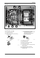
Installation
Mains contactor, fuses and cable cross-
sections
NOTE
Observe the following when using
earth−leakage circuit breakers:
Install earth−leakage circuit breakers only
between the supply mains and the frequency
inverter.
The earth−leakage circuit breaker may trip
incorrectly if several drives are
simultaneously connected to the mains.
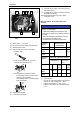
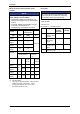
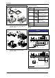
Frequency
inverter
Required mains
contactor K1
Type [kW] [kW] FI
2)
2FC4302-
1NE00
3 3
2FC4402-
1NE00
4 4
2FC4552-
1NE00
5,5 5,5
2FC4752-
1NE00
7,5 7,5
≥300 mA
Fuses and cable cross sections Frequency
inverter
Installation according
to EN 60204-1
Installation
according to
UL 1)
Type
L1, L2,
L3, PE
[mm
2
]
L1, L2,
L3, PE
[AWG]
2FC4302-
1NE00
M16
A
B16 A 2,5 15 A 14
2FC4402-
1NE00
M20
A
B20 A 4 20 A 12
2FC4552-
1NE00
M25
A
B25 A 4 25 A 10
2FC4752-
1NE00
M32
A
B32 A 6 35 A 8
Fuse
Circuit−breaker
1)
Use only UL−approved cables, fuses and fuse
holders. UL−fuse: voltage 500 ... 600 V,
tripping characteristic "H", "K5" or "CC"
2)
All−current sensitive e.l.c.b.
Relay data
NOTE
The service life of the relay depends on the
type of load (ohmic, inductive or capacitive)
and the value of the switching capacity.
Technical data
AC 250 V/3 A
DC 24 V/2 A … DC 240 V/0.22 A
Function Relay
position
switched
Displayed
message
X1/K11 Relay output
normally−close
d contact
opened TRIP
X1/K12 Relay
mid−position
contact
X1/K14 Relay output
normally−open
contact
closed TRIP
PES HF shield termination by large−surface
connection to PE