
Owner manual

© Gardner Denver Deutschland GmbH 25 / 52 610.44520.40.000
Installation
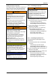
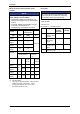
Relay data
NOTE
The service life of the relay depends on the
type of load (ohmic, inductive or capacitive)
and the value of the switching capacity.
Technical data
AC 250 V/3 A
DC 24 V/2 A ... DC 240 V/0.22 A
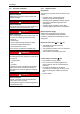
Function Relay
position
switched
Displayed
message
X1/K11 Relay output
normally−close
d contact
opened TRIP
X1/K12 Relay
mid−position
contact
X1/K14 Relay output
normally−open
contact
closed TRIP
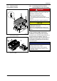
PES HF shield termination by large−surface
connection to PE
Connection
X1
5.3 mm
3/PE AC, 320 V ... 550 V, 45 ... 65 Hz
X1 L3 L2 BR2 K14L1 BR1 K12BR0 K11
PES
PES
0.5...0.6 Nm
4.4...5.3 lb-in
1.2...1.5 Nm
10.7...13.3 lb-in
ne2bhxn231
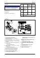
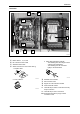
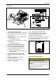
Fig. 13: Frequency inverter 2FC4152-1NE00 ... 2FC4222-1NE00 1 connecting
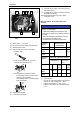
1 Connecting the mains cable:
A Release two screws at terminal X1 and
remove the terminal.
B Pass the mains cable through the cable gland.
C Attach the ring cable lug ( 5.3 mm) to the PE
conductor.
D Screw the PE conductor onto the PE stud for
the mains cable:
– observe tightening torque!
E Connect cores L1, L2 and L3 to X1 in correct
phase relation:
– observe tightening torque!
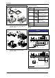
2 Wiring the relay output (if necessary):
A Pass the cable through the cable gland.
B Connect the shield of shielded cables
according to EMC requirements ( 24).
C Connect cores to terminal X1:
– observe terminal connection diagram and
tightening torque!
3 Re−insert terminal X1 and tighten with 2
screws:
– observe tightening torque!
4 Connecting the control cable shield:
A Pass the control cable through the cable
gland.
B Connect the shield according to EMC
requirements ( 24).
C Control cable connection: ( 29)
5 Tighten all cable glands.