Edition: 12.2009 · 610.44520.40.000 Original operating instructions · English Operating Instructions G-BH7e 2BH72..-..N 2BH73..-..N 2BH74..-..N 2BH75..-..N 2BH76..-..
Contents Contents Design of side channel blowers in conjunction with frequency inverters ........................................... 3 Quick start guide ................................................................................................................................ 4 1 Safety instructions ...............................................................................................................................5 1.1 Definitions ............................................................
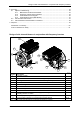
Design of side channel blowers in conjunction with frequency inverters 8 Servicing............................................................................................................................................43 8.1 Repair/ troubleshooting ...........................................................................................................43 8.1.1 Malfunctions at side channel blower ..........................................................................43 8.1.
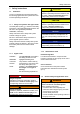
Quick start guide Quick start guide 6 Adjust the speed. A) Speed adjustment using a potentiometer Side channel blowers are pre-configured for four operating modes. It only takes a few steps and they are ready for operation: The speed is adjusted via the analog input. The speed can be adjusted between aminimum and a maximum value.Description of potentiometer wiring starts on page 30. ACHTUNG The drive motor is protected against overheating by a thermal detector.
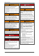
Safety instructions 1 Safety instructions 1.1 CAUTION Danger of injuries. Indicates a potentially hazardous situation, that may result in minor or moderate injury if the corresponding measures are not taken. Definitions To point out dangers and important information, the following signal words and symbols are used in these Operating Instructions: CAUTION 1.1.
Safety instructions WARNING DANGER! Improper use of the pump−motor unit can result in serious or even fatal injuries! Electrical danger! Do not open the frequency inverter until absence of electricity has been ensured! Only operate the pump−motor unit for the purposes indicated under "Application as directed"! with the media indicated under "Application as directed"! with the values indicated under "Technical data"! WARNING Danger due to vacuum and gauge pressure: sudden escape of media (s
Safety instructions WARNING Danger from rotating parts (motor fan, impeller, shaft): cutting/cutting off of extremities, grasping/winding up of hair and clothing! Danger due to vacuum and gauge pressure: sudden escape of media (skin and eye injuries), sudden drawing−in of hair and clothing! Danger due to escaping media: burns! Before beginning work on the pump−motor unit, take the following measures : Shut down pump−motor unit and secure against being switched on again.
Safety instructions WARNING CAUTION Danger zone: Missing or defective muffler on inlet or discharge connection. Hazard: Possible serious hearing damage due to emitted noise. Protective measures: Have missing or defective mufflers replaced. Conduct a noise measurement in the system after installing the pump−motor unit. The following measures must be taken by the operator: from 85 dB(A): – Hearing protection must be available. from 90 dB(A): – Mark noise area with a warning sign.
Safety instructions 1.4 Application as directed Validity of the Operating Instructions These Operating Instructions are valid for G-BH7e series side channel blower in conjunction with frequency inverters equipped with the following frequency inverters: 2FC 4 xxx - 1NE00 1x 35 2 Type 3 nash_elmo Industries GmbH Industriestrasse 26 D-97616 Bad Neustadt Supply voltage 4 = 400 V/500 V Prod.-ID Prod.-No. Version Ser.-No. Input Power (e.g.152 = 15 ´ 102 W = 1,5 kW) (e.g..
Safety instructions 1.5 Foreseeable Misuse It is prohibited to use the pump−motor units in applications other than industrial applications unless the necessary protection is provided on the system, e.g.
Technical data 2 2.1.2 Technical data 2.1 2.1.1 Measurement conditions Mechanical data Weights Type Weight approx. [kg] approx. [lbs] Single−impeller design 2BH7210−0.N1 20 44 2BH7210−0.N5 32 71 2BH7310−0.N2 20 44 2BH7310−0.N6 35 77 2BH7410−0.N1 27 60 2BH7410−0.N5 42 93 2BH7510−0.N2 39 86 2BH7510−0.N6 48 106 2BH7610−0.N3 45 99 2BH7220−0.N5 38 84 2BH7320−0.N5 40 88 2BH7320−0.N8 46 101 2BH7420−0.N2 43 95 2BH7420−0.N5 49 108 2BH7520−0.N7 61 134 2BH7620−0.
Technical data 2.1.3 Tightening torques for screw connections Temperature increase The information listed in the following tables corresponds to the heating of the side channel housing and the air exiting compared to the ambient temperature during operation with a permissible total pressure difference and an air pressure of 1013 mbar [14.7 psi]. At lower air pressures these values increase. Type The following values apply if no other data are given.
Technical data 2.3 General data/operating conditions Conformity CE Low−Voltage Directive Vibration resistance Acceleration resistant up to 2g (Germanischer Lloyd, general conditions) Vibration velocity max. veff 4 mm/s [0,013 ft/s] Depending on the application case and the system type it may be necessary to use vibration dampers. Site altitude min. 0 m üNN [0 ft amsl] max. 1000 m üNN [3280 ft amsl] For installations above 1000 m amslA [3280 ft amsl] consultation of the manufacturer is required.
Transport and handling 3 Transport and handling WARNING Tipping or falling can lead to crushing, broken bones etc.! Sharp edges can cause cuts! Wear personal safety equipment (safety gloves, safety shoes and safety helmet) during transport! WARNING Danger from lifting heavy loads! Manual handling of the pump−motor unit is only permitted within the following limits: max. 30 kg [max. 66 lbs] for men max. 10 kg [max. 22 lbs] for women max. 5 kg [max.
Transport and handling Type Type of transport manually with lifting appl. Single−impeller design 2BH7210−0.N1 X 2BH7210−0.N5 2BH7310−0.N2 X X 2BH7310−0.N6 2BH7410−0.N1 X X 2BH7410−0.N5 X 2BH7510−0.N2 X 2BH7510−0.N6 X 2BH7610−0.N3 X Two−impeller design 2BH7220−0.N5 X 2BH7320−0.N5 X 2BH7320−0.N8 X 2BH7420−0.N2 X 2BH7420−0.N5 X 2BH7520−0.N7 X 2BH7620−0.N3 X 2BH7620−0.N4 X Three−impeller design 2BH7630−0.N6 © Gardner Denver Deutschland GmbH X 15 / 52 610.44520.40.
Installation 4 Installation WARNING Improper use of the pump−motor unit can result in serious or even fatal injuries! Have you read the chapter "Safety instructions"? ( 5) Otherwise you may not carry out any work with or on the pump−motor unit! DANGER! Danger from missing view into area of pump−motor unit! When operating the control elements without a view into the area of the pump−motor unit, there is a danger that the pump−motor unit will be switched on while other persons are still performing wo
Installation CAUTION Danger of overheating due to hot surface of pump−motor unit! High temperatures can occur on the surface of the pump−motor unit. Temperature−sensitive parts, such as cables or electronic components, may not come into contact with the surface of the pump−motor unit. CAUTION Danger of pump−motor unit damage caused by penetration of foreign bodies! On delivery all connection openings are closed in order to prevent the penetration of foreign bodies.
Installation 4.1.2 Noise radiation Free spaces In order to reduce the noise radiation, CAUTION do not mount pump−motor unit on noise−conducting or noise−radiating parts (e.g. thin walls or sheet−metal plates). provide pump−motor unit with sound−insulating intermediate layers (e.g. rubber buffers under the base of the pump−motor unit) if necessary. install the pump−motor unit on a stable foundation or on a rigid mounting surface.
Installation 4.1.3 Mounting NOTE Dimensioned drawings with detailed dimensions, including fastening dimensions, are provided by the manufacturer. Horizontal installation ne2bhxn002c Fig. 5: Schematic diagram: installation on the cover of the side channel housing Mounting sequence: ne2bhxn002d Fig. 4: Schematic diagram: horizontal installation Mounting sequence: 1 Select suitable mounting elements.
Installation 1 Select suitable mounting elements. 2 Position the pump−motor unit as close to the wall as possible on a stable supporting plate with sufficient load−bearing capacity. – The pump−motor unit must be positioned with the base towards the wall. 2BH732 ... 2BH762 (two−impeller pump−motor units with two−stage design) 3 Attach the pump−motor unit to the wall: – Screw the base of the pump−motor unit to the wall via the mounting holes.
Installation 4.3.2 Rotation direction of the shaft The rotation direction of the shaft is marked by an arrow on the cover of the side channel housing and by an arrow on the fan guard of the motor. WARNING Danger from interchanging inlet and pressure line! Interchanged inlet and pressure lines can lead to damage to the pump−motor unit and the system, and as a result of this to serious injuries! Make sure that the inlet and the pressure line cannot be confused when connecting.
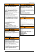
Installation 4.4 Electrical installation DANGER! Electrical danger! Malpractice can result in severe injuries and material damage! DANGER! Electrical danger! The electrical connection may be carried out by trained and authorized electricians only! DANGER! Electrical danger! Before beginning work on the pump−motor unit or system, the following measures must be carried out: Deenergize. Secure against being switched on again. Determine whether deenergized. Ground and short−circuit.
Installation 4.4.2 4.4.3 Preparing works Open frequency inverter Connecting frequency inverters 2FC4152-1NE00 and 2FC4222-1NE00 DANGER! 2FC4152-1NE00 ... 2FC4222-1NE00 Electrical danger! Improper connection of the pump−motor unit can result in an electric shock. Observe the following basic rules: The leakage current to earth (PE) is >3.5 mA. The PE connection must meet EN 50178. Observe national and regional regulations.
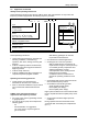
Installation X1 Terminal strip for mains connection and relay output connection 2FC4152-1NE00 ... 2FC4222-1NE00 D B C A X2 Terminal strip for motor connection and motor temperature monitoring PES HF shield termination by large−surface connection to PE X1 Mains contactor, fuses and cable crosssections NOTE X2 F E 1ne2bhxn101 Fig. 12: Terminal box 2FC4152-1NE00 ...
Installation Relay data Function NOTE X1/K11 Relay output normally−close d contact The service life of the relay depends on the type of load (ohmic, inductive or capacitive) and the value of the switching capacity. Relay position switched Displayed message opened TRIP closed TRIP X1/K12 Relay mid−position contact Technical data AC 250 V/3 A X1/K14 Relay output normally−open contact DC 24 V/2 A ... DC 240 V/0.
Installation NOTE Do not remove the jumper between terminals BR1 and BR0! Otherwise trouble−free functioning of the pump−motor unit cannot be guaranteed. 4.4.4 Connecting frequency inverters 2FC4302-1NE00 ... 2FC4752-1NE00 DANGER! Electrical danger! Improper connection of the pump−motor unit can result in an electric shock. Observe the following basic rules: The leakage current to earth (PE) is > 3.5 mA. The PE connection must meet EN 50178. Observe national and regional regulations.
Installation Realisation A B X1 G E H X2 D C F 2ne2bhxn398 Fig. 14: Electrical connections 2FC4302-1NE00 … 2FC4752-1NE00 Mains cable L1, L2, L3, PE 3 Insert cable and tighten cable tie: PE connection mains cable – Shielded control cable – Shield connection for the control cable: g: 1 Prepare cable.. The shielding must have large−surface contact to the shield sheet. The shielding must be connected tightly to the shield sheet. ne2bhxn047 ne2bhxn045 2 Insert cable tie..
Installation Relay data Mains contactor, fuses and cable crosssections NOTE NOTE The service life of the relay depends on the type of load (ohmic, inductive or capacitive) and the value of the switching capacity. Observe the following when using earth−leakage circuit breakers: Install earth−leakage circuit breakers only between the supply mains and the frequency inverter. The earth−leakage circuit breaker may trip incorrectly if several drives are simultaneously connected to the mains.
Installation Connection 3/PE AC, 320 V ... 550V, 45 ... 65 Hz 1.1 Nm 9.7 lb-in PES PES 4.3 mm X1 K14 K12 K11 L3 1.2...1.5 Nm 10.7...13.3 lb-in L2 L1 6 mm ne2bhxn431 Fig. 15: Connectiing frequency inverter 2FC4302-1NE00 ... 2FC4752-1NE00 1 Connecting the mains cable: A Pass the mains cable through the cable gland. B Attach the ring cable lug (Ø 4.3 mm) to the PE conductor. C Screw the PE conductor onto the PE stud for the mains cable: – observe tightening torque 4.4.
Installation Screw terminal data 2FC4152-1NE00 … 2FC4222-1NE00 Electrical Terminal strip with screw connection connections 1 Possible connections rigid: 1,5 mm2 (AWG 16) flexible: without wire end ferrule 1,0 mm2 (AWG 18) 2 without wire end ferrule, without plastic sleeve 0,5 mm2 (AWG 20) 3 C LA CK with wire end ferrule, with plastic sleeve 0,5 mm2 (AWG 20) ne2bhxn147 Fig.
Installation Terminal assignment X3/3 Signal type Function Level X3/62 Analog output Output frequency 0 ... + 6 V X3/7 - GND1, reference potential for analog signals - X3/8 Analog input Setpoint input Change setpoint selection range via DIP switch 0 ... +5 V (default setting) 0 ... +10 V 0 ... +20 mA X3/9 - Internal, stabilised DC voltage source for setpoint potentiometer +5,2 V (ref.: X3/7) X3/20 - Internal DC voltage source to control digital +20 V ± 10 % (ref.
Installation Electrical data of the terminals CAUTION X3/ X3/62 Resolution X3/8 Improper closing of the frequency inverter may damage the contacts of the control terminal module.
Installation 2FC4302-1NE00 … 2FC4752-1NE00 1.1 Nm 9.7 lb-in IP65 ne2bhxn459 Fig. 23: Close frequency inverters 2FC4302−1NE00 ... 2FC4752−1NE00 © Gardner Denver Deutschland GmbH 33 / 52 610.44520.40.
Commissioning 5 Commissioning WARNING Improper use of the pump−motor unit can result in serious or even fatal injuries! Have you read the chapter "Safety instructions"? ( 5) Otherwise you may not carry out any work with or on the pump−motor unit! WARNING Danger from rotating parts (motor fan, impeller, shaft): cutting/cutting off of extremities, grasping/winding up of hair and clothing! Danger due to vacuum and gauge pressure: sudden escape of media (skin and eye injuries), sudden drawing−in of hai
Commissioning 5.2 DANGER! Parameter setting 5.2.1 Electrical danger! Before beginning work on the pump−motor unit or system, the following measures must be carried out: Deenergize. Secure against being switched on again. Determine whether deenergized. Ground and short−circuit. Cover or block off adjacent energized parts. The hand-held keypad 2FX4506-0NE00 Description The hand−held keypad is available as accessories.
Commissioning Display elements and function keys Function Explanation Enable controller d c b e a j g f k i h PS m n op 8 8888 888 88888 q r Hi Lo v t z w x y m Hz V A %sh Ω°C rpm u s 0 1 2 3 Function keys 4 5 6 1 function bar 2 active To right/left in active The active function is function bar framed value n_e2fcx002 Only blinking values can be changed Fast change: Keep respective key pressed Store parameters Status displays when ! is blinking Confirmation by Store
Commissioning Changing and saving parameters All parameters for parameterization or monitoring of the controller are stored in codes. The codes are numbered and marked with a "C" in the documentation. The available codes are listed in the code table. Step Keys 1. Connect keypad Result Action XX.XX Hz The function is active. C0140 = setpoint is indicated via keypad. 2. Set parameters Select mode ". 3. XXXX Select code.. 4. Modus off Ahlen. 5.
Commissioning Code No. Possible settings Designation C0010 Minimum output frequency C0011 Maximum output frequency Manufacturer 10,00 Selection 0,00 {0,02 Hz} 650,00 C0010 only limits the analog input 1 Only valid for units 2BH.−..N.1−. 86,00 C0012 Acceleration time main setpoint IMPORTANT 7,50 {0,02 Hz} and 2BH.−..N.3−.with integrated 2FCxxxx−1NE00 inverter 650,00 Maximum permissible value: 86 (5000/min) Only valid for units 2BH.−..N.1−. 10,00 and 2BH.−..N.3−.
Commissioning 5.3 Start-up of the pump-motor unit The description of how to change pre-set parameters using the hand-held keypad starts on page 35. NOTE When no setpoint has been entered, the drive rotates with the minimum frequency set under C0010! The setpoint offset set under C0140 is stored and will be active at each switch−on.
Commissioning The base settings are now completed and the drive can be started: Start drive 12. Enter the setpoint. Note A) Using the keypad Set desired output frequency under C0140. The min. frequency under C0010 and the setpoint offset under C0140 are added! B) Using the potentiometer via terminals 7, 8, 9 C) Enter fixed speed via terminal. E3 E4 34 Hz (2000/min) Terminal HIGH LOW 67 Hz (4000/min) LOW HIGH 50 Hz (3000/min) HIGH HIGH 13. Enable controller.
Operation 6 Operation CAUTION WARNING Improper use of the pump−motor unit can result in serious or even fatal injuries! Have you read the chapter "Safety instructions"? ( 5) Danger of bearing damage! Heavy mechanical impacts must be avoided during operating and while at a standstill.
Shut-down and longer standstills 7 Shut-down and longer standstills CAUTION Danger of overheating due to high temperature! When storing in an environment with a temperature of over 40 °C [104 °F], the winding may be damaged and the grease change interval may be shortened.
Servicing 8 Servicing WARNING Improper use of the pump−motor unit can result in serious or even fatal injuries! Have you read the chapter "Safety instructions"? ( 5) Otherwise you may not carry out any work with or on the pump−motor unit! 8.1 8.1.
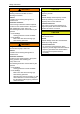
Servicing Malfunction Cause Remedy Side−channel blower does not reach the required speed / pump−motor unit does not generate pressure difference or generated difference is too low Leak in system. Seal leak in the system. Carried out by Operator Shaft seal defective. Replace shaft seal. Service*) Side channel blower operates, setpoints”0” Different density of pumped gas. Take account of the conversion of the pressure values. Service Inquire with Service Department.
Servicing 8.1.3 Fault indication at the keypad Keypad Malfunction (PC) ccr (71) Cause Remedy Carried out by 1) ce1 (62) ce2 (63) ce3 (64) System fault Strong interferences on control Shield control cables cables Ground or earth loops in the wiring Remove ground or earth loops. CAN−IN1 object receives faulty Check if the bus module is data or communication is correctly plugged on.
Servicing Keypad Malfunction (PC) LU Cause Remedy Carried out by Mains voltage too low Check mains voltage Electrician DC−bus voltage too low Check supply module 400 V frequency inverter connected to 230 V mains Connect frequency inverter to the correct mains voltage. Short−circuit Search for cause of short−circuit; Operator check motor cable. Electrician Excessive capacitive charging current of the motor cable Use shorter motor cable with lower charging current..
Servicing Keypad Malfunction (PC) Cause Remedy Carried out by Motor too hot because of excessive currents or frequent and too long accelerations Check dimensioning of side channel blower. Operator Impeller jammed Repair side channel blower. Service *) PTC or thermostat not connected or defective Connect or repair PTC or thermostat. Service Operator Mains voltage too high Reduce frequency inverter load.
Servicing 8.3 Decontamination and declaration of clearance WARNING Danger from flammable, caustic or toxic substances! To protect the environment and persons, the following applies: Pump−motor units which have come into contact with dangerous substances must always be decontaminated before being passed on to a workshop! To provide proof that the decontamination was carried out, a declaration of clearance must be included with the pump−motor unit on delivery to the workshop.
Disposal 9 Disposal Have the entire pump−motor unit scrapped by a suitable disposal company: Ensure recycling of metals and plastics. Assembled PCBs need to be disposed of professionally. For additional information on disposing of the pump−motor unit, ask the Service Department. © Gardner Denver Deutschland GmbH 49 / 52 610.44520.40.
Declaration of conformity Declaration of conformity EU declaration of conformity Manufacturer: Gardner Denver Deutschland GmbH P.O. Box 1510 D-97605 Bad Neustadt / Saale Responsible for documentation: Holger Krause P.O. Box 1510 D-97605 Bad Neustadt / Saale Designation: G series Side channel blower G-BH1e, G-BH7e Types 2BH1...-..N, 2BH7...-..N, 2BH1...-..L, 2BH7...-..
Form for statement on safety Form for statement on safety Statement on health safety and on the protection of the environment For the safety of our employees and to comply with statutory requirements on handling substances harmful to the health and the environment, this statement must be enclosed, fully completed, with each unit/system sent.
www.gd-elmorietschle.de er.de@gardnerdenver.com Gardner Denver Schopfheim GmbH Roggenbachstraße 58 79650 Schopfheim · Deutschland Tel. +49 7622 392-0 Fax +49 7622 392-300 Elmo Rietschle is a brand of Gardner Denver‘s Industrial Products Group and part of Blower Operations. Gardner Denver Deutschland GmbH Industriestraße 26 97616 Bad Neustadt · Deutschland Tel.