
Owner's manual

© Gardner Denver Deutschland GmbH 19 / 52 610.44521.40.000
Installation
Mounting sequence:
1 Select suitable mounting elements.
2 Position the pump−motor unit as close to the
wall as possible on a stable supporting plate
with sufficient load−bearing capacity.
– The pump−motor unit must be positioned
with the base towards the wall.
3 Attach the pump−motor unit to the wall:
– Screw the base of the pump−motor unit to
the wall via the mounting holes.
– When doing so, be sure to provide all
mounting holes with screws!
4 Remove the supporting plate.
4.1.4 Final works
After installing the pump−motor unit, the eye bolt
must be removed or screwed tightly.
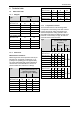
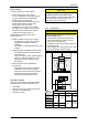
4.2 Mounting of the muffler
The pump−motor units are supplied with mufflers
for inlet and discharge connections as standard.
The mufflers are marked by arrows in the
following drawings.
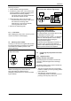
2BH1400 … 2BH180. (single−impeller
pump−motor units)
ne2bhxn004a
Fig. 7: Mounting of the muffler 2BH1400 … 2BH180.
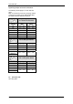
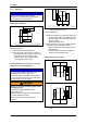
With the following pump−motor units, the
inlet−side muffler is included loose for
packaging−related reasons. It must be mounted
by the operator.
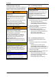
2BH1310 … 2BH1610 (two−impeller
pump−motor units with two−stage design)
ne2bhxn004b
Fig. 8: Mounting of the muffler 2BH1310 … 2BH1610
WARNING
Danger from rotating impeller:
cutting/cutting off of extremities!
The rotating impeller is accessible with the inlet
and discharge connections open!
With free entry and exit of gases, i.e. with direct
intake out of the atmosphere or direct feeding
into the atmosphere without piping, the
following therefore applies:
Provide the inlet and discharge connections of
the pump−motor unit either with additional
mufflers or with additional piping of a sufficient
length to prevent access to the impeller!
4.3 Connecting the pump-motor unit to the
system
4.3.1 Important notes
Delivery direction of the gases
The pumped gases are sucked in via the inlet
connection and discharged via the discharge
connection.
The delivery direction of the gases is marked by
arrows on the connections:
The inlet connection with the corresponding
muffler is marked by an arrow pointing into the
pump−motor unit.
The discharge connection with the
corresponding muffler is marked by an arrow
pointing out of the pump−motor unit.