
Owner's manual

© Gardner Denver Deutschland GmbH 11 / 52 610.44521.40.000
Technical data
2 Technical data
2.1 Mechanical data
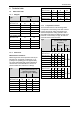
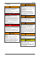
2.1.1 Weights
Weight Type
approx. [kg] approx. [lbs]
Single−impeller design
2BH1400-7.N1. 20 44
2BH1400-7.N2. 21 47
2BH1500-7.N3. 35 77
2BH1600-7.N3. 52 115
2BH180.-7.N0. 122 268
2BH180.-7.N1. 136 299
Two−impeller design
2BH1310-7.N2. 19 42
2BH1410-7.N4. 37 82
2BH1510-7.N5. 53 117
2BH1610-7.N3. 63 139
2BH1610-7.N4. 80 176
2.1.2 Noise level
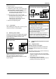
Measurement conditions
Measuring-surface sound-pressure level as per
EN ISO 3744, measured at a distance of 1 m
[3.28 ft] at an operating point of approximately
2/3 of the permissible total pressure difference
with the lines connected without a vacuum or
pressure relief valve, tolerance 3 dB (A).
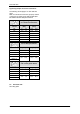
1−m measuring−surface
sound−pressure level L for
operation with output
frequency approx. [dB (A)]
Type
50 Hz 60 Hz 86 Hz
Single−impeller design
2BH1400-7.N1. 63 64 74
2BH1400-7.N2. 63 64 74
2BH1500-7.N3. 64 70 75
2BH1600-7.N3. 69 72 80
2BH180.-7.N0. 70 74 81
2BH180.-7.N1. 70 74 81
Two−impeller design
2BH1310-7.N2. 55 61 66
2BH1410-7.N4. 66 69 77
2BH1510-7.N5. 72 74 83
2BH1610-7.N3. 73 76 84
2BH1610-7.N4. 73 76 84
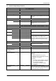
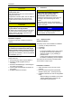
2.1.3 Temperature increase
The information listed in the following tables
corresponds to the heating of the side channel
housing and the air exiting compared to the
ambient temperature during operation with a
permissible total pressure difference and an air
pressure of 1013 mbar [14.7 psi]. At lower air
pressures these values increase.
Temperature increase for
operation with output
frequency
50 Hz
approx.
60 Hz
approx.
86 Hz
approx.
Type
∆T
[K]
∆υ
[F]
∆T
[K]
∆υ
[F]
∆T
[K]
∆υ
[F]
Single−impeller design
2BH1400-7.N1. 54 129 50 122
2BH1400-7.N2. 65 149 75 167
2BH1500-7.N3. 95 203 82 180
2BH1600-7.N3. 107 225 85 185
2BH180.-7.N0. 40 104 40 104
2BH180.-7.N1. 67 153 85 185
≤
120
≤
248
Two−impeller design
2BH1310-7.N2. 53 127 74 165
2BH1410-7.N4. 83 181 82 180
2BH1510-7.N5. 90 194 94 201
2BH1610-7.N3. 80 176 75 167
2BH1610-7.N4. 105 221 88 190
≤
120
≤
248