
Manual

Installation and Commissioning
610.44431.40.000 14 / 30 © Gardner Denver Deutschland GmbH
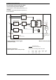
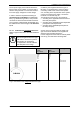
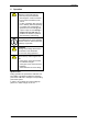
Fig. 6: External electronics
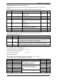
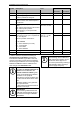
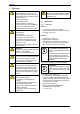
Fig. 7: Connector pin assignment and mating connector
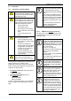
If there is no connector (mating connector to the
external electronics) connected to the motor ca-
ble of the G-BH100, the loose lead ends are sur-
rounded by an ESD-prevention bag. In this case,
the socket connector must first be connected to
the motor cable.
i
IMPORTANT!
The motor of the G-BH100 including
its connecting leads must be pro-
tected against electrostatic dis-
charge (ESD).
Do not remove the ESD-prevention
bag surrounding the lead ends until
right before carrying out the electri-
cal connection (attaching the con-
nector, connecting to a terminal strip,
or the like)!
Carry out the electrical connection
using the appropriate ESD-
prevention equipment!
92
80
3
6,5
84
112
13
Control sig-
nal connector
(X3)
Motor-
connector
(X4)
PAPST
Drivecontrol VT-D
Gardner Denver Deutschland GmbH-Ident.-Nr.:
519_00082_01_000
S
+
Not
used
+Ub
87
6
5
4
321
S
-
Gnd IST
B
Slot for lug
A
8 7
6
5
4
3 2 1
RLG3 Gnd L1 L2
Slot for lug
RLG1 RLG2 +U
Hall
L3
Control signal connections
(X3)
Mating connector type:
MOLEX - 39-01-2085
Moto
r
connections
(X4)
Mating connector type:
MOLEX - 39-01-2085
432
1
8
76
5
lug
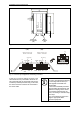
Mating connector
(connected to motor cable)