
Manual

Installation and Commissioning
© Gardner Denver Deutschland GmbH 13 / 30 610.44431.40.000
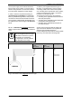
Supply voltage/ control signal connection side:
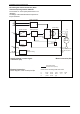
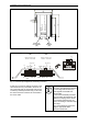
The connector for supply voltage / control signal connection (connector X3) is shown in Fig. 7,
page 14.
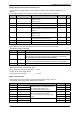
On the supply voltage / control signal connection side the assignment is as follows:
Symbol Description Lead colour Pin
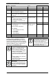
A Mode of operation States:
1 (High): 5…24 V
0 (Low): < 0.5 V
white Pin 1
+U
B
+ Operating voltage 38 ... 52 V red Pin 2
- Not used violet Pin 3
n
Soll
(S
+
) Speed reference value Control voltage: 0…10 V
Reference value of the desired speed of the
G-BH100.
green Pin 4
B Mode of operation States:
1 (High): 5…24 V
0 (Low): < 0.5 V
grey Pin 5
IST Actual speed (optional) Open Collector output
Here the rotor speed can be read
yellow Pin 6
Gnd - Operating voltage 0 V black Pin 7
S
-
Ground Set Value input 0 V brown Pin 8
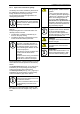
Via the digital control inputs A and B the direction/mode of operation is determined.
The following states are possible:
Level A Level B Mode of operation
0 0 Output stage disabled (no current).
0 1 Counter-clockwise rotation
(according to the arrow indicating the direction of rotation on the pump lid):
Main / operating direction of rotation of the G-BH100!
1 0 Clockwise rotation
(opposed to the arrow indicating the direction of rotation on the pump lid):
1 1 Breaking
Please take also note of the following data:
Wire cross section of the connecting cable 0.5 mm²
Control current on the supply voltage /
control signal connection side
max. 9 A
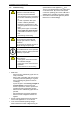
Motor connection side:
The connector for motor connection (connector X4) is shown in Fig. 7, page 14.
On the motor connection side the assignment is as follows:
Symbol Description Lead colour Pin
L1 Motor phase 1 brown Pin 6
L2 Motor phase 2 violet Pin 5
L3 Motor phase 3
Terminals of the motor windings.
Operating voltage: 48 V against electronics
max. winding peak current: 13 A
max. winding temperature: 115°C
yellow Pin 1
RPD1 Hall signal 1 green Pin 4
RPD2 Hall signal 2 white Pin 3
RPD3 Hall signal 3
Rotor position detectors.
Hall ICs with open collector output.
They must be wired to an external pull-up
resistor.
grey Pin 8
+V
Hall
Hall supply red Pin 2
Gnd
Hall
Hall supply
Feeder line of the hall ICs.
black Pin 7