
Manual

Installation and Commissioning
610.44431.40.000 12 / 30 © Gardner Denver Deutschland GmbH
Purchasing the external electronics (Drive-
control VT-D) along with the G-BH100
For the order no. of this option please refer to our
catalogue.
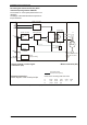
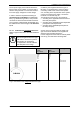
The design of the external electronics (Drivecon-
trol) is as follows:
Fig. 5: External electronics: block diagram of the control principle
external electronics
(commercial component)
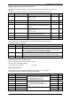
Colours of the connecting leads of the motor:
L1 brown RLG1 green Gnd
Hall
black
L2 violet RLG2 white +V
Hall
red
L3 yellow RLG3 grey
Supply voltage / control signal
connection (X3)
External electronics:
Block diagram of the control principle
MOTOR
PWM-generation
Speed controller
Speed
evaluation
Commutation-
logic
internal
signal processing
Output stage
Current
measurement
Mode of operation
Rotor position detecto
r
RLG1, RLG2, RLG3
Gnd
Hall
+V
Hall
L1
L2
L3
+
-
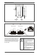
Motor connection (X4)
Gnd
IST
(MF-PIN)
n
Soll
+U
B
A
B