Edition: 04.2010 · 610.44431.40.000 Original Operating Instructions · English Operating Instructions G-BH10 2BH10 02-.AB32 2BH10 02-.AB22 2BH10 02-.
Table of Contents Table of Contents 1 2 3 Safety and Residual Risks.......................................................................................................... 3 Intended Use .............................................................................................................................. 5 Technical Data............................................................................................................................ 6 3.1 Nominal and Limiting Values Pump ..............
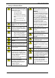
Safety and Residual Risks 1 Safety and Residual Risks Before beginning to work on the GBH100 or the system carry out the following steps for both the G-BH100 and the entire system – switch off electricity, – lock against restart, – ensure absence of electricity, – ground and short-circuit installation, – cover or bar adjacent live parts, – depressurise both pipes and pump.
Safety and Residual Risks i The motor of the G-BH100 including its connecting leads must be protected against electrostatic discharge (ESD).
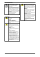
Intended Use 2 Intended Use These operating instructions must be completely read and understood by all operating and servicing personnel before beginning to work with or on the G-BH100, must be strictly observed, must be available at the site of operation of the G-BH100, applies to Side channel blowers of the G-Series G-BH100, contains instructions bearing on transport and handling, installation, commissioning, operation, servicing, shut-down, and storage of the G-BH100.
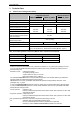
Technical Data 3 3.1 Technical Data Nominal and Limiting Values Pump G-BH100 with enclosed motor and integrated electronics 2BH10 02-_AB32 Weight external electronics 2BH10 02-_AB22 1.2 kg [2.65 lbs] Dimensions 2BH10 02-_AA53 1.5 kg [3.31 lbs] see Fig. 1 & Fig. 2, page 8 Sound level2 48 dB(A) 51 dB(A) 55 dB(A) 100 mbar 105 mbar 185 mbar 105 mbar 105 mbar 190 mbar max. permissible total differential pressure3 at +15°C: - vacuum pump operation4 5 - compressor operation max.
Technical Data 3.2 Nominal and Limiting Values Motor and Electronics G-BH100 with enclosed motor and integrated electronics 2BH10 02-0AB32 Voltage range Nominal voltage Max. input current Nominal speed Speed control range Rated power external electronics 2BH10 02-0AB22 2BH10 02-0AA53 14...28 V DC 38...52 V DC 24 V DC 48 V DC 4.5 A 5.2 A 7.
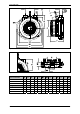
Technical Data Fig. 1: Dimensions of the 2BH1002-0…. (hose connection) Fig. 2: Dimensions of the 2BH1002-1…. (flange connection) d1 d2 E F G G1 K R2 19 53 72 11 1 450 4.2 19 53 72 11 1 450 4.2 20 19 53 92 11 1 450 4.2 60 20 19 53 72 11 1 450 4.2 95 60 20 19 53 72 11 1 450 4.2 95 60 20 19 53 92 11 1 450 4.
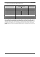
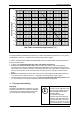
Transport and Handling 1.01 1 0.99 Conversion factor 0.98 0.97 0.96 0.95 0.94 0.93 0.92 0.91 -20 0 -10 10 20 30 40 50 Gas intake and ambient temperature t [°C] Fig. 3: Permissible total differential pressure / conversion factor For the permissible total differential pressure at an intake and ambient temperature of +15°C [+59°F] see the table in section 3.1, "Nominal and Limiting Values Pump", page 6.
Installation and Commissioning 5 5.
Installation and Commissioning 5.2 5.2.1 Connection i Electrical Connection (Motor) WARNING! Work on electrical installations may be carried out by trained and authorised electricians only! WARNING! Before beginning any electrical work on the G-BH100 or the system carry out the following steps for both the G-BH100 and the entire system – switch off electricity, – lock against restart, – ensure absence of electricity, – ground and short-circuit installation, – cover or bar adjacent live parts. 5.2.1.
Installation and Commissioning Purchasing the external electronics (Drivecontrol VT-D) along with the G-BH100 For the order no. of this option please refer to our catalogue.
Installation and Commissioning Supply voltage/ control signal connection side: The connector for supply voltage / control signal connection (connector X3) is shown in Fig. 7, page 14. On the supply voltage / control signal connection side the assignment is as follows: Symbol Description Lead colour Pin A Mode of operation States: 1 (High): 5…24 V 0 (Low): < 0.5 V white Pin 1 +UB + Operating voltage 38 ...
Installation and Commissioning 92 112 84 13 Drivecontrol VT-D PAPST 3 6,5 Gardner Denver Deutschland GmbH-Ident.-Nr.: 519_00082_01_000 80 Control signal connector (X3) Motorconnector (X4) Fig.
Installation and Commissioning The scope of supply of the external electronics (Drivecontrol VT-D) includes a connector with a 300 mm wiring harness to connect the Drivecontrol to the supply voltage and control voltage. In order to meet the requirements bearing on electromagnetic compatibility a suitable EMI filter (e.g. CORCOM, Type 6ET1, 10A) must be connected in series with the external-electronics. The connecting cable between the EMI filter and the G-BH100 must have a length of at maximum 0,3 m. 5.2.
Installation and Commissioning Symbol Description Level Lead colour Cable old version Cable new version +UB DC operating voltage 24 V (max. 28 V) pink red Gnd DC operating voltage, reference potential for all signals 0V yellow black ndes Speed reference value: Reference value of the desired speed of the G-BH100. 0 ... 10 V DC green green nact Frequency output representing the actual Open collector max.
Installation and Commissioning 5.2.
Installation and Commissioning 5.
Operation 6 Operation WARNING! Operation of the G-BH100 only: with the pump lid assembled with the pipes / hoses connected to the suction and delivery branches or in case of operation with open suction or delivery branches (drawingin of gases from or discharge of gases into the surroundings) with a piece of pipe or hose having a length of at least 120 mm connected to the branch in question with the bearing end housing i IMPORTANT! The G-BH100 must not be operated with the suction or delivery branc
Servicing 7 Servicing WARNING! Before beginning to work on the GBH100 or the system carry out the following steps for both the G-BH100 and the entire system switch off electricity, lock against restart, ensure absence of electricity, ground and short-circuit installation, cover or bar adjacent live parts, depressurise both pipes and pump. WARNING! Work on electrical installations may be carried out by trained and authorised electricians only! 7.1 7.1.
Servicing 3 1 4 1 2 3 4 Bolts Impeller Pump lid Impeller nut 2 Fig. 9: Disassembly/ assembly of the pump lid 7.1.2 7.1.3 Inspection Carry out the following tasks on the G-BH100 at regular intervals: Fastening to the mounting surface: Tighten fixing bolts. Fastening torque: according to property class 8.8 of the bolts or nuts used as given in ISO 898 Cable entry: Tighten screwed cable glands. Fastening torques: - on casing side: Tf = 3.2 Nm ± 0.2 - on cable side: Tf = 1.5 Nm ± 0.
Servicing 7.2 Repair/ Troubleshooting Fault Cause Motor does not start, no motor noise. At least two power supply Check fuses, terminals and supply leads and leads interrupted. close circuit where interrupted. Electrician No signal at control signal Apply control signals, see section 5.2.1, inputs A and B. "Electrical Connection (Motor)", page 11. Electrician No speed reference value Set speed reference value, see section 5.2.1, given. "Electrical Connection (Motor)", page 11.
Shutting Down and Measures for Prolonged Standstill 8 Shutting Down and Measures for Prolonged Standstill i IMPORTANT! If the storage period exceeds one year the life expectancy of the bearings might be reduced. Measures after shutdown / before storage: Seal up the suction and delivery branches. Provide loose lead ends with an ESDprevention bag. Ensure the correct storage conditions (see below). Storage conditions: Ambient temperature -20°C...+70°C (-4°F…+158°F) Relative humidity 10% ...
EC Declaration of Conformity EC Declaration of Conformity EU declaration of conformity Manufacturer: Gardner Denver Deutschland GmbH P.O. Box 1510 D-97605 Bad Neustadt / Saale Responsible for documentation: Holger Krause P.O. Box 1510 D-97605 Bad Neustadt / Saale Designation: G series Side channel blower G-BH10 Types 2BH10 02-.AB32 2BH10 02-.AB22 2BH10 02-.
© Gardner Denver Deutschland GmbH 25 / 30 610.44431.40.
610.44431.40.
© Gardner Denver Deutschland GmbH 27 / 30 610.44431.40.
610.44431.40.
© Gardner Denver Deutschland GmbH 29 / 30 610.44431.40.
www.gd-elmorietschle.de er.de@gardnerdenver.com Gardner Denver Schopfheim GmbH Roggenbachstraße 58 79650 Schopfheim · Deutschland Tel. +49 7622 392-0 Fax +49 7622 392-300 Elmo Rietschle is a brand of Gardner Denver‘s Industrial Products Group and part of Blower Operations. Gardner Denver Deutschland GmbH Industriestraße 26 97616 Bad Neustadt · Deutschland Tel.