
Manual


9
Technical data
610.00260.40.000 · 05.2014
64 / 74
© Gardner Denver Deutschland GmbH
Technical data
General data
Technical data 400 V devices
Size MA MB MC MD
Recommended motor power
(4 -pin asynchronous motor)
1,5 2,2 3,0 4,0 5,5 7,5 11,
0
15,
0
18,
5
22,
0
A
mbient temperature
-25°C [-13°F] (non-condensing) up to +50°C [+122°F] (without derating) *
Mains voltage[V] 3~ 400 -10%
–
480 +10%
Mains frequency [Hz] 4
–
63
Line system configurations TN/TT
Mains current [A] 3,3 4,6 6,2 7,9 10,8 14,8 23,
3
28,
3
33,
3
39,
9
Rated current, effective
[IN at 8 kHz / 400 V]
4,0 5,6 7,5 9,5 13,0 17,8 28,
0
34,
0
40,
0
48,
0
Minimum braking resistance
[Ω]
100 50 50 30
Maximum overload 150% of rated current for 60 s 13
0%
Switching frequency [kHz] 4, 8, 16 (factory setting 8)
Cyclic frequency [Hz] 0
–
400
Protection function Over/undervoltage, I
2
t limitation, short circuit, motor inverter temperature,
anti-tilt protection, anti-lock system
Process control Freely configurable PID controlle
r
Dimensions
L x B x H [mm]
233 x 153 x 120 270 x 189 x 140 307x223x181 414 x 294 x 232
Weight including adapter
plate [kg]
3,9 5,0 8,7 21,0
Protection class [IPxy] 65 55
EMC met according to DIN EN 61800-3, class C2
*according to UL standard 508C, see Approval according to UL [➙ 73].
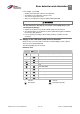
Designation Function
Digital inputs 1-4 - Switching level low < 5V / high > 15
V
- Imax (at 24 V) = 3mA
- Rin = 8.6 kOhm
A
nalogue inputs 1, 2 - Input +/- 10V or 0 - 20mA -
input 2 - 10V or 4 - 20mA
- resolution 10 bit
- Rin = 10kOhm
Digital outputs 1, 2 - Short-circuit-proof
- Imax = 20 mA
Relay 1, 2 1 changeover contact (NO/ NC)
maximum switching power*:
- for resistive load (cos j = 1): 5 A ~ 230 V or 30 V
- at inductive load (cos j = 0.4 and L/ R = 7 ms): 2 A ~ 230 V or = 30 V
maximum response time: 7 ms ± 0.5 ms
electric service life: 100,000 switching cycles
A
nalogue output 1 (current) - Short-circuit-proof
- I output = 0 to 20 mA
output load = 500 Ohm
9
9.1