
Manual


Parameters
7
© Gardner Denver Deutschland GmbH
57 / 74
05.2014 · 610.00260.40.000
I
2
T
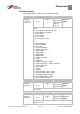
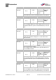
33,010 I
2
T factor of the motor Unit: %
Relationship to
parameter:
33.031
33.101
Parameter HB:
S. xy
Transfer
status:
2
min: 0 Intrinsic value
(to be en-
tered!)
max: 1000
Def: 0
Here, the percentage of current threshold (based on the motor
current 33,031) can be adjusted at the start of integration.
33,011 I
2
T time Unit: s
Relationship to
parameter:
33,100
Parameter HB:
S. xy
Transfer
status:
2
min: 0 Intrinsic value
(to be en-
tered!)
max: 1200
Def: 25
Time after which the drive controller turns off with I
2
T.
33,138 Holding current time Unit: s
Relationship to
parameter:
33,100
Parameter HB:
S. xy
Transfer
status:
2
min: 0 Intrinsic value
(to be en-
tered!)
max: 128000
Def: 2
Only for asynchronous motors.
Is the time interval during which the drive is maintained with
direct current after stoppage of the braking ramp.
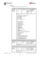
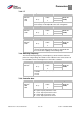
Switching frequency
The internal switching frequency (clock frequency) can be varied to control the
power unit. A high setting value leads to noise reduction in the motor, but also to
increased EMC emission and higher losses in the drive controller.
34.030 Switching frequency Unit: Hz
Relationship to
parameter:
Parameter HB:
S. xy
Transfer
status:
2
min: 1 Intrinsic value
(to be en-
tered!)
max: 4
Def: 2
Selecting the switching frequency of the inverter.
1 = 16 kHz
2 = 8 kHz
4 = 4 kHz
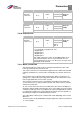
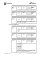
Controller data
34.010 Control mode Unit: Integer
Relationship to
parameter:
33.001
34.011
Parameter HB:
S. xy
Transfer
status:
2
min: 100 Intrinsic value
(to be en-
tered!)
max: 201
Def: 100
Selection of the control mode.
100 = open -loop asynchronous motor
101 = close- loop asynchronous motor
200 = open-loop synchronous motor
201 = close- loop synchronous motor
7.4.2
7.4.3
7.4.4