
Manual


Parameters
7
© Gardner Denver Deutschland GmbH
47 / 74
05.2014 · 610.00260.40.000
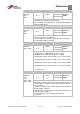
3,062 – 3,068 PID fixed setpoints Unit: %
Relationship to
parameter:
1.100
1.130
Parameter HB:
S. xy
Transfer
status:
2
min: 0 Intrinsic value
(to be en-
tered!)
max: 100
Def: 0
Fixed PID setpoint values that should be output at the digital
inputs 1 – 3 set in parameter 3,069, depending on the switching
pattern (must be selected in parameter 1,130).
3,069 Fixed PID setpoint mode Unit: integer
Relationship to
parameter:
1.100
3.062 – 3.068
Parameter HB:
S. xy
Transfer
status:
2
min: 0 Intrinsic value
(to be en-
tered!)
max: 2
Def: 0
Selection of the digital inputs used for the fixed frequencies.
0 = digital input 1 (fixed PID setpoint 1) (3,062)
1 = digital input 1, 2 (fixed PID setpoint 1-3) (3,062 - 3,064)
2 = digital input 1, 2, 3 (PID fixed setpoint 1-7) (3,062 - 3,068)
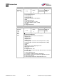
3,070 PID standby time Unit: s
Relationship to
parameter:
1,020
Parameter HB:
S. xy
Transfer
status:
2
min: 0 Intrinsic value
(to be en-
tered!)
max: 10000
Def: 0
If the drive controller runs the set time at its minimum frequency
(parameter 1,020), the motor is stopped (0 Hz), see also PID
process control, Explanation of operating modes [➙ 36].
0 = disabled
>0 = wait time until the activation of the standby function
3,071 PID standby hysteresis Unit: %
Relationship to
parameter:
3,060
Parameter HB:
S. xy
Transfer
status:
2
min: 0 Intrinsic value
(to be en-
tered!)
max: 50
Def: 0
Wake-up condition of the PID controller from the standby func-
tion.
If the control deviation is greater than the set value in %, the
control restarts, see also operating modes of PID controller.
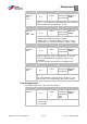
Analogue inputs
For analogue inputs 1 and 2 (AIx - illustration AI1/AI2)
4.020/4.050
A
Ix input type Unit: Integer
Relationship to
parameter:
Parameter HB:
S. xy
Transfer
status:
2
min: 1 Intrinsic value
(to be en-
tered!)
max: 2
Def:
4.020 1
4.050 2
Function of the analogue inputs 1/2.
1 = voltage input
2 = current input
7.3.5