
Manual


Installation
5
© Gardner Denver Deutschland GmbH
25 / 74
05.2014 · 610.00260.40.000
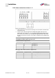
Terminal no. Designation (Terminal) assignment
15
A
. Out 0 ... 10
V
A
ctual frequency value (parameter
4,100)
16
A
GND (Ground 10 V) Ground
17
A
. In 1 External Setpoint source (parameter
1,130)
18
A
GND (Ground 10 V) Ground
19
A
. In 2
A
ctual PID value (parameter 3,060)
20
A
GND (Ground 10 V) Ground
Terminal assignment X6 (relay 1)
Terminal no. Designation (Terminal) assignment
1 COM Centre contact relay 1
2 NO Normally open contact relay 1
3 NC Normally closed contact relay 1
In the factory setting, relay 1 is programmed as "fault relay" (parameter
4,190).
Terminal assignment X7 (relay 2)
Terminal no. Designation (Terminal) assignment
1 COM Centre contact relay 2
2 NO Normally open contact relay 2
3 NC Normally closed contact relay 2
In the factory setting, relay 2 is programmed as "fault relay" (parameter
4,210).
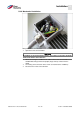
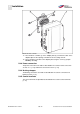
Wiring diagram
Control terminals
The drive controller is ready for operation after connection to a 400 V AC power
supply (to the terminals L1 to L3) or after connection to a 565 V DC power supply
(to the terminals L1 and L3).
Alternately, there is the option to put the drive controller in operation by connect-
ing an external 24 V voltage.
The required presetting is described in the chapter "System parameters".
5.3.7