Edition 05.2014 · 610.00260.40.000 Operating Instructions 2FC4...-1ST | 2FC4...-1PB | 2FC4...-1PN | 2FC4...-1SC | 2FC4...
Contents 1 2 2.1 2.2 2.3 2.4 3 3.1 3.2 3.2.1 3.2.2 3.2.3 3.2.4 3.2.5 3.2.6 3.2.7 3.3 3.4 3.5 4 4.1 4.2 4.3 5 5.1 5.2 5.2.1 5.2.2 5.2.3 5.2.4 5.2.5 5.2.6 5.3 5.3.1 5.3.2 5.3.3 5.3.4 5.3.5 5.3.6 5.3.7 5.4 5.4.1 5.4.2 5.4.3 5.4.4 5.4.5 6 6.1 6.2 6.3 610.00260.40.000 · 05.2014 Overview of sizes ......................................................................... Further information ...................................................................... Storing the documentation ...........................
Contents 6.4 6.4.1 6.4.2 7 7.1 7.2 7.2.1 7.2.2 7.3 7.3.1 7.3.2 7.3.3 7.3.4 7.3.5 7.3.6 7.3.7 7.3.8 7.3.9 7.3.10 7.3.11 7.3.12 7.4 7.4.1 7.4.2 7.4.3 7.4.4 7.4.5 7.4.6 8 8.1 8.2 9 9.1 9.2 9.2.1 9.2.2 9.2.3 10 10.1 10.2 10.3 11 11.1 11.2 11.3 11.4 Commissioning steps ..................................................................... Start up the integrated drive control .............................................. Commission the drive control wall assembly and replacement ..... Parameters ...............
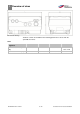
1 Overview of sizes 1Overview of sizes Dimensional drawings The drive controls are available in the following performance classes with the specified size names. Sizes Sizes drive controls motor integrated Recommended motor power [kW] Dimensions L x B x H [mm] 610.00260.40.000 · 05.2014 MA MB MC MD 1.5 2.2 / 3.0 / 4.0 5.5 / 7.5 233 x 153 x 120 270 x 189 x 140 307 x 223 x 181 11.0 / 15.0 / 18.5 / 22.
Further information 2 2Further information 2.1 Storing the documentation Store this manual and all other applicable documents safely so they are available as and when required. Provide the operator of the system with this manual so it is available as and when required. 2.2 Explanation of the terms and symbols In these instructions symbols and terms will be used to mean the following.
2 Further information Term Plant Vacuum pump/compressor Motor Compressor Assembly environment Drive control Explanation Part provided by the user in which the vacuum pump/compressor is installed. Ready to connect machine for the generation of a vacuum and/or overpressure. The vacuum pump/compressor consists of a compressor part and motor, as well as other accessories where applicable. Asynchronous motor for driving the vacuum pump/compressor. Mechanical part of the vacuum pump/compressor without motor.
Safety and responsibility 3 3Safety and responsibility The manufacturer is not liable for damage caused by the failure to observe these instructions and the related documents [➙ 6]. 3.1 Explanation of warning signs Warning sign Explanation Danger that failure to observe the measures could lead to death or serious physical injuries. Danger that failure to observe the measures could lead to death or serious physical injuries.
3 Safety and responsibility NOTICE The drive controller may be operated safely only if the required ambient conditions are met, see Suitable ambient conditions [➙ 15]. NOTICE This operating manual must be kept in the vicinity of the equipment, so as to be readily accessible to all users. NOTICE Please read these safety instructions and warnings carefully and all the warning labels attached to the equipment before installing and commissioning.
Safety and responsibility 3 3.2.3 Commissioning DANGER Risk of injury due to electric shock! The non-observance of warnings can result in severe bodily injury or substantial property damage. 1. Only hard-wired grid connections are permitted. The device must be earthed (DIN EN 61140; VDE 0140-1). 2. The drive controls may have contact currents > 3.5mA. According to DIN EN 61800-5-1 chapter 4.3.5.5.
3 Safety and responsibility 3.2.4 Operation DANGER Risk of injury from electric shock or restarting motors! The non-observance of warnings can result in severe bodily injury or substantial property damage. Observe the following instructions during operation: The drive controller operates at high voltages. When operating electrical equipment, certain parts of the equipment carry dangerous voltage.
Safety and responsibility 3 Measurement of insulation resistance on the power unit In the course of the series testing, the power unit of the drive controller is tested by applying 1.9 kV.
3 Safety and responsibility 3.2.7 Disassembly and Disposal Screw and snap-on connections are easy to release and allow the drive control to be dismantled into its individual parts. These parts can be sorted for recycling. Please comply with local regulations during disposal. Components with electronic parts may not be disposed of along with normal household waste. They have to be collected separately with used electrical and electronic equipment in accordance with applicable legislation. 3.
Safety and responsibility 3 3.5 Requirements of the operator As a basic principle, electronic devices are not fail-proof. The operator and/or the contractor setting up the machine or system is responsible for ensuring that the drive switches to a safe state if the device fails. The “Electrical equipment of machines” section in EN 60204-1, “Safety of machinery” describes the safety requirements for electrical control units.
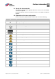
4 Product identification 4Product identification 4.1 Model description Item designation 1 2FC = drive control 2 Connection voltage: 4 = 400 V -15% — 480 V +10% 3 Performance: 152 = 1.5 kW 222 = 2.2 kW 302 = 3.0 kW 402 = 4.0 kW 552 = 5.5 kW 752 = 7.5 kW 4 Type of assembly: 1 = integrated drive control 5 Version: ST = Standard PB = Profibus PB = Profinet SC = Sercos III CB = CANopen 6 reserved: 0 = Standard 4.
Installation 5 5Installation 5.1 Safety instructions for installation WARNING 1. Installation may only be performed by appropriately qualified employees who are trained in the set-up, installation, start-up and operation of the product. Work performed on the drive control by unqualified staff and non-observance of warnings may result in serious injury or damage. 2. The device must be grounded in accordance with EN 61140, NEC and other relevant standards. Mains connections must be hardwired. 5.
5 Installation 5.2.2 Suitable installation location for the motor-integrated drive control Ensure that the motor with a motor-integrated drive control is only installed and operated if aligned as shown in the following diagram. Motor installation location/permitted alignments 5.2.
Installation 5 Unused open cable ends in the motor connection box must be insulated. If a PTC or Klixxon is used, the jumper, seated in the terminal for the PTC in the delivery condition, must be removed. The cross section of the mains supply line should be designed according to the type of wiring and the max. current allowed. The mains supply protection must be ensured by the system start-up engineer. 5.2.
5 Installation 5.2.6 Preventing electromagnetic interference For control circuits shielded cables must be used, where possible. At the cable end, the shield should be applied with due care without leaving the wires unshielded over longer distances. The shielding of analogue setpoints should only be applied on one side of the drive controller. Basically, the control wires should always be routed as far away as possible from power cables; separate cable ducts may have to be used, if required.
Installation 5 The standard adapter plate is an adapter plate whose lower part has not been refinished. No holes are drilled. For the motors supplied, you can order adapter plates from the manufacturer. 5. Adjust them to the adapter plate (1) by drilling appropriate holes (2) in them for attachment to the motor. The system start-up engineer is responsible for maintaining the protection class for the gasket of the adapter plate on the motor. For questions, please contact your sales representative. 6.
5 Installation 5.3.2 Mechanical installation of size D For mechanical installation of the drive controller, proceed as follows: 1. Open the standard motor connection box. 2. Remove the fastening screws securing the housing and remove the housing. Be careful not to damage the gasket.
Installation 5 when mounting the adapter plates, ensure that all four screws, including the spring elements are tightened by applying the correct torque! All contact areas must be dirt/ paint-free, as correct protective earth connection cannot be ensured otherwise. 6. Reattach the original terminal board (8) to the motor, possibly with the aid of the terminal board expansion option (7) and the elongated screw option (9). 7.
5 Installation 5.3.3 Power connection of sizes A - C Power connection BG A - C 1. 2. Unscrew the four screws from the housing cover of the drive controller and remove the cover. Run the mains cable through the threaded cable gland and connect the phases with the contacts L1, L2, L3 for 400 V and the buried cable with the PE contact on the terminal.
Installation 5 5.3.4 Power connection of size D Power connection BG D 1. 2. Unscrew the four screws from the housing cover of the drive controller and remove the cover. Run the mains cable through the threaded cable gland and connect the phases with the contacts L1, L2, L3 for 400 V and the buried cable with the PE contact on the terminal.
5 Installation 5.3.5 Connections for braking resistor Terminal assignment for braking chopper Terminal no. 1 2 Designation B+ B- (Terminal) assignment Connection of braking resistor (+) Connection of braking resistor (-) 5.3.6 Control terminals Control terminals of the standard application card NOTICE Risk of coupling of external signals! Use shielded control wires. 1. 2. 3. Pass the required control wires through the threaded cable glands into the housing.
Installation 5 Terminal no. 15 Designation A. Out 0 ... 10 V 16 17 A GND (Ground 10 V) A. In 1 18 19 20 A GND (Ground 10 V) A. In 2 A GND (Ground 10 V) (Terminal) assignment Actual frequency value (parameter 4,100) Ground External Setpoint source (parameter 1,130) Ground Actual PID value (parameter 3,060) Ground Terminal assignment X6 (relay 1) Terminal no.
5 Installation 5.4 Installing the wall-mounted drive controller 5.4.1 Installation location that is suitable for wall mounting ! Please make sure that the installation location for wall mounting meets the following conditions: 1. The drive controller must be mounted on a flat, solid surface. 2. The drive controllers may only be mounted on non-combustible surfaces. 3. There must be at least a 20-cm-wide clearance all around the drive controller to ensure free convection.
Installation 5 5.4.2 Mechanical installation Wiring at the motor connection box 1. Open the motor connection box. NOTICE Depending on the desired motor voltage, star or delta connection should be made in the motor connection box. 2. 3. 4. When connecting the shielded motor cable to the motor connection box, use suitable EMC fittings and ensure proper (large surface) contact with the shield. Connecting a PE connection to the motor connection box is mandatory. Reconnect the motor connection box.
5 Installation Mounting the adapter plate to a wall WARNING Risk of injury due to incorrect assembly! The drive controller may not be installed without an adapter plate. 5. Find a location that corresponds to the required ambient conditions, as described in the "Installation requirements" section. 6. In order to achieve optimum self-convection of the drive controller, it must be ensured during assembly that the (EMC) fitting points upward. 7.
Installation 5 Wiring 8. 9. 10. 11. 12. 13. Loosen the screw (1) to remove the contact plate from the adapter plate. Below this contact plate is the (M6x15) PE connection (3). Lead the connection cable from the motor via the integrated EMC fitting into the adapter plate. This PE connection (torque: 4.0 Nm [2.95 ft lbs]) must be connected to the same earth potential of the motor. The cross section of the equipotential bonding conductor must correspond to at least the cross-section of the mains cable.
5 Installation Mount the drive controller 14. Place the drive controller (1) on the adapter plate (2) such that the collar of the adapter dips into the opening at the bottom of the cooling element. 15. Secure the drive controller to the adapter plate using the screws (3) (torque: 4.0 Nm [2.95 ft lbs]). 5.4.3 Power connection The power connections are made as described in the sections Power connection of sizes A - C [➙ 22] and Power connection of size D [➙ 23]. 5.4.
Commissioning 6 6Commissioning 6.1 Safety information for commissioning WARNING Risk of injury! The non-observance of warnings can result in severe bodily injury or substantial property damage. 1. Make sure that the power supply provides the correct voltage and is designed for the necessary current. 2. Use suitable circuit breaker with the specified nominal current between the mains supply and drive controller. 3.
6 Commissioning 6.2 Communication The drive controller can be put into operation in the following ways: ▪ using the PC software PC software - start screen ▪ via the hand-held unit MMI MMI hand-held unit 610.00260.40.000 · 05.
Commissioning 6 6.3 Block diagram General structure setpoint generation © Gardner Denver Deutschland GmbH 33 / 74 05.2014 · 610.00260.40.
6 Commissioning 6.4 Commissioning steps The drive control can be parameterised on the motor prior to installation. To this end, the drive controller has a 24-V low-voltage input, which powers the electronic parts, and without which a mains voltage must be supplied. Commissioning can be done with a USB PC communication cable to connector M12 with integrated RS485/RS232 interface converter (2FC4521-0ER00) or via the MMI hand-held unit, including connection cable RJ11 to connector M12 (2FX4520-0ER00). 6.4.
Commissioning 6 4. 5. 6. 7. Perform motor identification. Implement application settings (ramps, inputs, outputs, setpoints, etc.). Optional: Define access level (1 - HAND-HELD UNIT MMI, 2 - user 3 - manufacturer). Once all settings have been implemented, with a high signal on terminal strip X5 through the hardware release (En-HW) on terminal no. 10 and software release on terminal no. 6 (digital input 1), the drive control can be put into operation (e.g. control via analogue input 1 with 0-10 V).
7 Parameters 7Parameters In this chapter, you will find ▪ an introduction to the parameters ▪ an overview of the most important commissioning and operating parameters 7.1 Safety instructions for handling the parameters WARNING Risk of injury from restarting motors! The non-observance of warnings can result in severe bodily injury or substantial property damage.
Parameters 7 PID inverse: Inversion of the PID feedback can be done with the help of parameter 3,061. The actual value is read inverted, i.e. 0V…10V correspond internally to 100% ... 0%. Please bear in mind that the setpoint should also be specified inversely! An example: A sensor with an analogue output signal (0V…10V) is to be operated as the actual value source (at AIx). At an output quantity of 7V (70%), it should be regulated inversely. The internal actual value then corresponds to 100% - 70% = 30%.
7 Parameters Standby function for PID process control Fixed frequency: In this operating mode, fixed frequency setpoints are passed on to the motor control. There are 7 fixed frequencies (2,051 - 2,057) which are linked in BCD format to the digital inputs 1 to 3. These seven fixed frequencies can be enabled via the parameter "Auswahl_Festfrequenz(Selection_fixed_frequency)" (2,050) into three groups: 0 = fixed frequency 1, 1 = fixed frequency 1 to 3, 2 = fixed frequency 1 to 7.
Parameters 7 7.2.2 Structure of parameter tables Example of parameter table 1 Parameter number 2 6 Unit Description in the parameters manual on page... 7 Box for entering the inherent value 3 Parameter name 8 Explanation of the parameters Transfer status 0 = turn on and off to take over 4 the drive controller 1 = at speed 0 2 = in operation 9 5 © Gardner Denver Deutschland GmbH Other parameters related to this parameter Range of values (from - to - factory setting) 39 / 74 05.2014 · 610.
7 Parameters 7.3 Application parameter 7.3.1 Basic parameters 1,020 Minimum frequency Unit: Hz Relationship to Parameter HB: Transfer min: 0 Intrinsic value parameter: status: (to be enmax: 400 1.150 S. xy tered!) Def: 25 3.070 2 The minimum frequency is the frequency that is supplied by the drive controller as soon as it is released and no additional setpoint is pending. This frequency is not reached if a) it is accelerated from the stationary drive. b) the FI is locked.
Parameters 7 1,052 Braking time 2 Unit: s Relationship to Parameter HB: Transfer min: 0.1 Intrinsic value parameter: status: (to be enmax: 1000 1.021 S. xy tered!) Def: 10 1.054 2 The braking time 2 is the time it takes for the inverter to decelerate from the max. frequency (1,021) to 0 Hz. If the set braking time cannot be met, the fastest possible braking time is implemented. 1,053 Power-up time 2 Unit: s Relationship to Parameter HB: Transfer min: 0.
7 Parameters 1,130 Setpoint source Unit: integer Relationship to Parameter HB: Transfer min: 0 Intrinsic value parameter: status: (to be enmax: 10 3,062 – 3,069 S. xy tered!) Def: 1 2 Specifies the source from which the setpoint is to be read.
Parameters 7 1,132 Non-tarnish protection Unit: integer Relationship to Parameter HB: Transfer min: 0 Intrinsic value parameter: status: (to be enmax: 6 1,131 S. xy tered!) Def: 0 2 Selection of characteristics on the control release (parameter 1,131). No effect if autostart was selected.
7 Parameters 1,180 Acknowledgement function Unit: integer Relationship to Parameter HB: Transfer min: 0 Intrinsic value parameter: status: (to be enmax: 5 1.181 S. xy tered!) Def: 3 1.182 2 Selects the source for the error acknowledgement. Errors can only be acknowledged if the error is no longer present. Certain errors can only be acknowledgement by switching the controller on and off, see list of errors.
Parameters 7 2.051 – 2.057 Fixed frequency Unit: Hz Relationship to Parameter HB: Transfer min: -400 Intrinsic value parameter: status: (to be enmax: +400 1.020 tered!) Def: 1.021 2.051: 34 1.100 2.052: 67 1.150 2.053: 50 2.050 The frequencies that should be output at the digital inputs 1 - 3 set in parameter 2,050, depending on the switching pattern. See fixed frequency, Explanation of operating modes [➙ 36]. 7.3.3 Motor potentiometer This mode must be selected in parameter 1,130.
7 Parameters 2.154 MOP retentive Unit: Integer Relationship to Parameter HB: Transfer min: 0 Intrinsic value parameter: status: (to be enmax: 1 S. xy tered!) Def: 0 2 Determines whether the setpoint of the motor potentiometer is retained even after power failure. 0 = disabled 1 = enabled 7.3.4 PID process controller This mode must be selected in parameter 1,100, the setpoint source must be selected in parameter 1,130, see also fixed frequency, Explanation of operating modes [➙ 36].
Parameters 7 3,062 – 3,068 PID fixed setpoints Unit: % Relationship to Parameter HB: Transfer min: 0 Intrinsic value parameter: status: (to be enmax: 100 1.100 S. xy tered!) Def: 0 1.130 2 Fixed PID setpoint values that should be output at the digital inputs 1 – 3 set in parameter 3,069, depending on the switching pattern (must be selected in parameter 1,130). 3,069 Fixed PID setpoint mode Unit: integer Relationship to Parameter HB: Transfer min: 0 Intrinsic value parameter: status: (to be enmax: 2 1.100 S.
7 Parameters 4.021/4.051 AIx Norm. Low Unit: % Relationship to Parameter HB: Transfer min: 0 Intrinsic value parameter: status: (to be enmax: 100 S. xy tered!) Def: 0 2 Specifies the minimum value of the analogue inputs as a percentage of the final range value. Example: 0... 10V or 0... 20 mA = 0 %... 100% 2... 10V or 4... 20mA = 20%... 100% 4.022/4.052 AIx Norm. High Unit: % Relationship to Parameter HB: Transfer min: 0 Intrinsic value parameter: status: (to be enmax: 100 S.
Parameters 7 4.033/4.063 AIx - physical unit Unit: Relationship to Parameter HB: Transfer min: 0 Intrinsic value parameter: status: (to be enmax: 10 4.034/4.064 S. xy tered!) Def: 0 4.035/4.065 2 Selection of the different physical variables to be displayed. 0=% 1 = bar 2 = mbar 3 = psi 4 = Pa 5 = m3/h 6 = l/min 7 = °C 8 = °F 9=m 10 = mm 4.034/4.064 Alx physical minimum Unit: Relationship to Parameter HB: Transfer min: -10000 Intrinsic value parameter: status: (to be enmax: +10000 4.033/4.063 S.
7 Parameters 7.3.7 Analogue output 4.100 AO1 function Unit: Integer Relationship to Parameter HB: Transfer min: 0 Intrinsic value parameter: status: (to be enmax: 40 4.101 S. xy tered!) Def: 5 4.102 2 Selection of the process value that is output at the analogue output. Depending on the process value selected, the standard (4,101/4,102) must be adapted.
Parameters 7 7.3.8 Digital outputs For the digital outputs 1 and 2 (DOx - illustration DO1/DO2) 4.150/4.170 DOx function Relationship to Parameter HB: Transfer parameter: status: 4.151/4.171 S. xy 4.152/4.172 2 Unit: Integer min: 0 Intrinsic value (to be enmax: 50 tered!) Def: 4.150: 18 4.170: 19 Selection of the process variable to which the output should switch.
7 Parameters 7.3.9 Relay For the relays 1 and 2 (Rel. x - illustration rel. 1/rel. 2) 4.190/4.210 Rel.x function Relationship to Parameter HB: Transfer parameter: status: 4.191/4.211 S. xy 4.192/4.212 2 Unit: Integer min: 0 Intrinsic value (to be enmax: 50 tered!) Def: 4.190: 11 4.210: 0 Selection of the process variable to which the output should switch.
Parameters 7 4.193/4.213 Rel. x-on delay. Unit: s Relationship to Parameter HB: Transfer min: 0 Intrinsic value parameter: status: (to be enmax: 10000 4.194/4.214 S. xy tered!) Def: 0 2 Specifies the duration of the closing delay. 4.194/4.214 Rel. x off delay Unit: s Relationship to Parameter HB: Transfer min: 0 Intrinsic value parameter: status: (to be enmax: 10000 4.193/4.213 S. xy tered!) Def: 0 2 Specifies the duration of the turn-off delay. 7.3.10 External error 5.010/5.
7 Parameters 5.070 Motor current limit Relationship to Parameter HB: Transfer parameter: status: 5.071 S. xy 33.031 2 0 = disabled min: 0 max: 250 Def: 0 5.071 Motor current limit Relationship to Parameter HB: Transfer parameter: status: 5.070 S. xy 33.031 2 min: 0 max: 100 Def: 1 Unit: % Intrinsic value (to be entered!) Unit: s Intrinsic value (to be entered!) 5.075 Transmission factor Unit: Relationship to Parameter HB: Transfer min: 0 Intrinsic value parameter: status: (to be enmax: 10000 33.034 S.
Parameters 7 7.4 Power parameters 7.4.1 Motor data 33.001 Motor type Unit: Integer Relationship to Parameter HB: Transfer min: 1 Intrinsic value parameter: status: (to be enmax: 2 33.010 S. xy tered!) Def: 1 1 Selection of the motor type 1 = Asynchronous motor 2 = Synchronous motor Depending on the motor type selected, the corresponding parameters are displayed. The control mode (parameter 34,010) must also be chosen accordingly. 33.
7 Parameters 33.050 Stator resistance Relationship to Parameter HB: Transfer parameter: status: S. xy 1 Unit: Ohm min: 0 Intrinsic value (to be enmax: 30 tered!) Def: Typespecific Here, the stator resistance can be optimised if the automatically determined value (on the motor identification) is not sufficient. 33.105 Leakage inductance Unit: H Relationship to Parameter HB: Transfer min: 0 Intrinsic value parameter: status: (to be enmax: 100 S. xy tered!) Def: 0 1 Only for asynchronous motors.
Parameters 7 7.4.2 I2T 33,010 I2T factor of the motor Unit: % Relationship to Parameter HB: Transfer min: 0 Intrinsic value parameter: status: (to be enmax: 1000 33.031 S. xy tered!) Def: 0 33.101 2 Here, the percentage of current threshold (based on the motor current 33,031) can be adjusted at the start of integration. 33,011 I2T time Unit: s Relationship to Parameter HB: Transfer min: 0 Intrinsic value parameter: status: (to be enmax: 1200 33,100 S.
7 Parameters 34.011 Encoder type Unit: Integer Relationship to Parameter HB: Transfer min: 0 Intrinsic value parameter: status: (to be enmax: 2 34.010 S. xy tered!) Def: 0 34.012 2 34.013 Selection of encoder type. 0 = inactive 1 = TTL encoder 2 = HTL encoder NOTICE! When selecting the HTL encoder, 24V is outputted over the interface. This could lead to the destruction of the encoder when using a TTL encoder. 34.
Parameters 7 34.110 Slip trimmer Unit: Integer Relationship to Parameter HB: Transfer min: 0 Intrinsic value parameter: status: (to be enmax: 1 33.034 S. xy tered!) Def: 0 2 Only for asynchronous motors. Using this parameter, the slip compensation can be optimised or disabled. 0 = disabled (behaviour as on the mains) 1 = the slip is compensated. 34.130 Voltage control reserve Unit: Relationship to Parameter HB: Transfer min: 0 Intrinsic value parameter: status: (to be enmax: 2 S.
7 Parameters 34.226 Starting current Unit: % Relationship to Parameter HB: Transfer min: 5 Intrinsic value parameter: status: (to be enmax: 1000 34.227 S. xy tered!) Def: 25 2 Only for synchronous motors. The flow which is set in the motor prior to its start can be adjusted here. Value in % of the rated motor current. 34.227 Initialisation time Unit: s Relationship to Parameter HB: Transfer min: 0 Intrinsic value parameter: status: (to be enmax: 100 34.226 S.
Error detection and elimination 8 8Error detection and elimination In this chapter, you will find ▪ Display of the LED flash codes for error detection ▪ Description of error detection using PC tools ▪ List of errors and system errors ▪ Notes on error detection using the HAND-HELD UNIT MMI WARNING Risk of injury and danger of electric shock! The non-observance of warnings can result in severe bodily injury or substantial property damage. 1. Repairs on the device may only be carried out by the manufacturer.
8 Error detection and elimination 8.2 List of errors and system errors When an error occurs, the inverter switches off; for the corresponding error numbers, refer to the flash code table or the PC tool. Error messages can only be acknowledged when the error is no longer present. ! Error messages can be acknowledged as follows: 1. Digital input (programmable) 2. via the hand-held unit MMI 3. Automatic acknowledgement (parameter 1,181) 4. Switching the device on and off 5.
Error detection and elimination 8 No. 13 Error name External error 1 14 External error 2 15 Motor recognition 16 IGBT trip 17 18 19 20 21 22 23 24 25 26 27 28 29 30 Error description The parametrised error input is active. 5.010 The parametrised error input is active. 5.
9 Technical data 9Technical data 9.
Technical data 9 Designation Analogue output 1 (voltage) Voltage supply 24 V Voltage supply 10 V Function - Short-circuit-proof - Uoutput = 0..10V - Imax = 10 mA - Auxiliary voltage U = 24 V DC - short-circuit-proof - Imax = 100 mA - external 24 V supply possible - Auxiliary voltage U = 10 V DC - short-circuit-proof - Imax = 30 mA *According to UL standard 508C, max. 2 A is permitted 9.
9 Technical data 9.2.1 Derating through increased ambient temperature Derating for motor-mounted drive controllers (all sizes) Derating for wall-mounted drive controllers (sizes A - C) Derating for wall-mounted drive controllers (size C with optional fan and size D) 610.00260.40.000 · 05.
Technical data 9 9.2.2 Derating due to installation altitude The following applies to all drive controllers: ▪ In S1 mode, no power reduction is required up to 1,000 m above sea level. ▪ In the range from 1,000 m up to and including 2000 m, power reduction of 1% is required for every 100 m installation altitude.
9 Technical data 9.2.3 Derating due to the clock frequency The following illustration shows the output current as a function of the clock frequency. In order to limit the heat losses in the drive controller, the output current must be reduced. Note: There is no automatic reduction of the clock frequency! The max. output values can be defined, based on the following characteristic curve. Derating of the maximum output current due to the clock frequency 610.00260.40.000 · 05.
Optional accessories 10 10Optional accessories In this section, you will find brief descriptions of the following optional accessories ▪ Adapter plates ▪ Hand-held unit MMI, including connection cable RJ11 to connector M12 10.1 Adapter plates For each DRIVE CONTROLLER size, there is a standard wall-mounted adapter plate (with integrated adapter board for BG A to BG C). Download the 3D files for the drive controller and adapter plates at www.gdelmorietschle.com.
10 Optional accessories Drill pattern of standard wall-mounted adapter plate BG C Drill pattern of standard wall-mounted adapter plate BG D 610.00260.40.000 · 05.
Optional accessories 10 10.2 Hand-held unit MMI, including 3 m connection cable RJ11 to connector M12 The hand-held unit MMI 2FX4520-0ER00 is a purely industrial product (accessory) which may only be used in conjunction with a DRIVE CONTROLLER! The HANDHELD UNIT MMI is connected to the integrated M12 interface of the drive controller. By means of this control unit, the user is able to write (program) and/or display all parameters of the drive controller.
11 Guidelines, norms and standards 11Guidelines, norms and standards This chapter contains information about electromagnetic compatibility (EMC), and guidelines, norms and standards. For binding information about the relevant drive control approvals, please refer to the relevant type plate! 11.1 EMC limit classes Please note that EMC limit classes are only reached if the standard switching frequency (clocking frequency) of 8 kHz is complied with.
Guidelines, norms and standards 11 11.4 Approval according to UL Required Markings For installation on industrial machines in accordance with the Standard for Industrial Machinery NFPA79 for recognized components, and NFPA70 for listed components, only. Please check the drives’ name plate for further details. Maximum Ambient Temperature: Electronic INV MA 2 0.37 INV MA 2 0.55 INV MA 2 0.75 INV MA 2 1.1 INV MA 4 1.5 INV MB 4 2.2 INV MB 4 3.0 INV MB 4 4.0 INV MC 4 5.5 INV MC 4 7.