302 W est Beardsley Ave. • Elkhart, IN USA 46514 • 574.295.8330 • F ax 574.293.9914 Installation, Operating & Maintenance Instructions Model 294-11-CW and 294-11-CWB 98443000 Rev.
I. Product Safety 1. All Personnel who may be expected to use this equipment must be thoroughly trained in its safe and proper use. 2. Before flowing water from this device, check that all personnel (fire service and civilian) are out of the stream path. Also, check to make sure stream direction will not cause avoidable property damage. 3. Become thoroughly familiar with the hydraulic characteristics of this equipment, and the pumping system used to supply it.
II. Installation Instructions 1. How to Determine Nozzle Reaction Force It is important to note that the piping must be able to withstand a horizontal force of at least 1-1/2 times the nozzle reaction force at the height of the vertical swivel joint center and from any angle of rotation that the monitor is capable of turning. The nozzle reaction formula for smooth bore nozzles is NR = 1.5 x d2 x NP The nozzle reaction formula for combination fog nozzles is NR = 0.
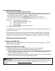
Figure 1 Improper Flange Installation 3. Chain Installation on monitor (0.250” non-magnetic aluminum chain required, McMaster Carr part number 3620T21) a) Vertical movement (1) Remove spring clip (item #12 on attached drawing) P/N 57681 (2) Slide chain wheel guide off shaft (3) Find middle point on length chain and hang onto the Chainwheel (4) Slide chain wheel guide back onto shaft (5) Reinstall spring clip b) Horizontal movement (1) Repeat above steps 1-5 4.
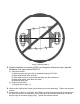
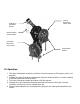
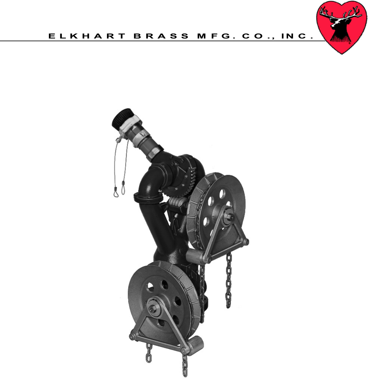
CJ-B-RC or CJN-B-RC Nozzle Vertical Movement Chain wheel Stream Pattern Control Cables Horizontal Movement Chain wheel Chain Wheel Guides III. Operation 1. The upper Chainwheel controls the monitor’s vertical movement of 150 degrees (+90 to -60 degrees) 2. Rotating the upper Chainwheel clockwise will raise the nozzle elevation, a counter clockwise movement lowers the nozzle elevation 3. The lower Chainwheel rotates the monitor a full 360 degrees. 4.
IV. Maintenance 1. Monitor should be inspected on a monthly basis. 2. Careful inspection should be conducted after use during emergency operations. 3. Exercise monitor by moving it thru its entire range of motion once a month to assure that monitor is operating properly, preferably with water flowing at the rated volume and pressure. 4. Inspect gearing for proper lubrication.
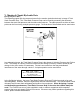
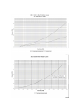
V. Monitor & Nozzle Hydraulic Data Interpreting Flow Data The following graphs offer the pressure losses for the monitor (and other devices) in terms of Total Static Pressure Drop. This Total Static Pressure Drop can be found by measuring the difference between the static inlet pressure and the static outlet pressure. The static pressure at either of these points can be found using a simple pressure gauge. An illustration of this method can be seen below.
Elkhart Brass Mfg. Co., Inc. Mailing Address: P.O. Box 1127 Elkhart, IN 46515 USA Shipping Address: 1302 W. Beardsley Ave. Elkhart, IN 46514 USA Tel. 1-574-295-8330 1-800-346-0250 Fax 1-574-293-9914 e-mail: info@elkhartbrass.com www.elkhartbrass.