
User guide

11
Installation Step 3: Program Settings
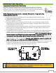
RF Receiver/Control Module Settings –
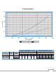
The SW1 switch is used for choosing the monitor programming. The SW4 switch has been factory
preset for position “E”. This setting allows for slow horizontal travel for the first 2-3 seconds before
switching to full speed. Changing to setting “8” allows full speed at all times (see Table 3, reference 4
on page 16).
This monitor has been equipped with mechanical hard-stops to prevent horizontal over-travel (see
Installation Step 4: System Programming). The hard-stops are permanently fixed by a stop screw and
milled slot in the base. Follow the programming steps to set all travel limits as prescribed in Installation
Step 4.
NOTE: The horizontal limits must be set to stop the motors at the location of the hard-stops.
E
8593-04 Copperhead RF – Blinking – Stow Indicator & Slow Start-up
8
8593-04 Copperhead RF – Fast Start-up
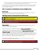
NOTE: When setting is changed power to the monitor must be cycled OFF/ON.
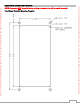
If it is set to a value that is not yet programmed, the status indicator LED, DS5 (see Figure 1), will blink
rapidly until a valid setting is selected AND power is cycled. If SW4 is set to a valid setting but not one
of the above positions, unpredictable results will occur.
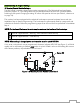
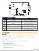
Figure 1: RF Receiver/Control Module Circuit Board
DS5
DS2
B
A
DS1
SW4
SW1
DS4
P2
DS3
P3
DS6
P1
P4
SW2
SW3
Status LED
SW4