8593-04 Monitor Installation, Operating, & Maintenance Instructions 1302 WEST BEARDSLEY AVE • ELKHART, IN 46514 • 574-295-8330 • 800-346-0250 © 2014 ELKHART BRASS MFG. CO., INC. • WWW.ELKHARTBRASS.
TABLE OF CONTENTS PRODUCT SAFETY INFORMATION 3 MONITOR CALLOUT DRAWING 4 SYSTEM COMPONENTS 5 INSTALLATION INSTRUCTIONS 8 Installation Step 1: Mount and Wire all System Components 8 Installation Step 2: Communication Address Setup 10 Installation Step 3: RF Settings Setup 11 Installation Step 4: System Programming 13 OPERATING INSTRUCTIONS 14 MAINTENANCE INSTRUCTIONS 16 SYSTEM SPECIFICATIONS 18 MONITOR AND NOZZLE HYDRAULIC DATA 19 COMPONENT MOUNTING TEMPLATES 21 To view the most cur
PRODUCT SAFETY INFORMATION All personnel who may be expected to use this equipment must be thoroughly trained in its safe and proper use. Before flowing water from this device, check that all personnel (fire service and civilian) are out of the stream path. Also, check to make sure stream direction will not cause avoidable property damage. Become thoroughly familiar with the hydraulic characteristics of this equipment, and the pumping system used to supply it.
MONITOR CALLOUT DRAWING Optional SM-1250BE Electronically Actuated Nozzle 282-B Stream Shaper 2.
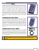
SYSTEM COMPONENTS MONITOR Copperhead RF Monitor – 8593-04 The 8593-04 Copperhead RF is a brass monitor that contains a central vane inside the waterway to minimize large-scale turbulence and provide superior fire streams. The water supply is provided through the monitor base by a 3” 150# flat faced flange. The discharge nozzle connection is a 2½“ National Hose Thread.
CONTROL Handheld RF Controller – 81282001 A sealed handheld RF transmitter contains all the controls necessary for operation of the monitor. The handheld remote allows the operator to direct the monitor from a significantly improved point of view. With the wireless remote, the operator can view the stream from the side and confirm that the stream is hitting its target. Separate push button switches are provided for up, down, left, right, fog, and stream functions.
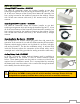
MONITOR ACCESSORY Primary OEM RF Transmitter – 81353101 The OEM RF transmitter allows the monitor installer to use their switching arrangement while still having the benefit of the W.E.T. It has all of the same features of the Primary Panel Mount RF controller, but has a wiring harness for the installer to connect to the switches. Comes with 10 foot coax antenna cable and (1) 90° antenna and (1) straight antenna.
INSTALLATION INSTRUCTIONS Installation Overview: Step 1 – Mount and Wire All System Components Step 2 – Communication Address Step 3 – Program Settings Step 4 – System Programming Installation Step 1: Mount and Wire All System Components Warning: It is up to the system designer to appropriately handle the open circuit condition of the stow signal. In the open circuit mode there is no source to turn off the stow signal load, which may lead to erroneous signal indications if not handled properly.
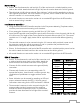
Monitor Wiring – Place a 10A fuse between the red lead (pin C) of the monitor and a switched positive power lead on the vehicle. Attach the black lead (pin A) from the monitor base to the vehicle ground. The white lead (pin B) is for an optional “Stow Indicator” which could be attached to a relay or LED supplied by the OEM. The circuit switches in a ground, and is limited to 250 mA of current when the monitor is in a non-stowed position.
Secondary Switch Box Control – Using the Secondary Control Switch Box template in the Component Mounting Templates section, mark the mounting holes on panel or bracket. Drill two 9/32” diameter holes in panel or bracket. Remove ¼-20 screws and lock washers from back of box. Insert screws with lock washers through backside of panel or bracket into mounting holes in box. Tighten screws.
Installation Step 3: Program Settings RF Receiver/Control Module Settings – The SW1 switch is used for choosing the monitor programming. The SW4 switch has been factory preset for position “E”. This setting allows for slow horizontal travel for the first 2-3 seconds before switching to full speed. Changing to setting “8” allows full speed at all times (see Table 3, reference 4 on page 16).
Installation Step 4: System Programming Programming Horizontal Limits & Stow Position The 8593-04 Copperhead RF monitor must show H2 limits relative to mounting flange. The monitor is shipped from the factory with horizontal limits at 180° (90° left and 90° right of the straight ahead position). The vertical limits are provided by magnets placed in the monitor at assembly and are not adjustable. NOTE: All programming steps must be completed. Otherwise the changes will not be stored to permanent memory.
OPERATING INSTRUCTIONS Normal Operation The 8593-04 Copperhead RF Monitor uses the standard Left/Right, Up/Down, and Fog/Stream commands to provide stream direction and pattern adjustments. With SW4 in position “E”, The controller provides an automatic speed adjustment to allow the user better directional control. During normal operation, the horizontal motor will move slowly for about two seconds before accelerating to full speed.
The monitor will oscillate between the limits until the oscillation button is pressed again. Pressing the left or right button on one of the controllers will also stop the oscillation. For safety reasons, once oscillation has stopped the oscillation limits need to be reprogrammed before it can be re-engaged. The nozzle fog, stream, and discharge elevation functions can be operated while the monitor is oscillating. NOTE: It is recommended to set oscillation between the maximum left/right travel limits.
MAINTENANCE & INSPECTION Monitor Preventive Maintenance The complete monitor and control system should be inspected during each apparatus check. Careful inspection for damage to the monitor or nozzle is especially important after use in emergency operations, and after extended use in salt water environments. Operate all possible functions to ensure that each works normally with each controller. Flow water to check the nozzle pattern.
DS4 DS3 DS2 DS6 SW1 DS1 SW3 DS5 P1 P4 B SW4 P3 P2 A SW2 Figure 5: System LED Notations Table 3: DS5 Status Indicator LED Table Reference 1 2 3 4 5 Indication Meaning Light comes on for 1 second when Motor has reached stall current and monitor stops performing normal shutdown. Blinks 3 times after pressing and holding Limit/stow programming sequence initiated. Red Programming Button for more than 5 NOTE: This must be completed before normal seconds. monitor operation is allowed.
SYSTEM SPECIFICATIONS Panel Mount Controller Input power RF power output Transmitter dimensions Operating temperature range Environmental Rating FCC ID 12/24 VDC (11 VDC to 30 VDC) Meets FCC part 15 requirements for license free operation 7 5/8” x 3 7/8” x 2 3/8” -40oC to +65oC, -40oF to +150oF NEMA 4 QT8PTSS2011 Handheld Controller Input power RF power output Transmitter dimensions Transmitter weight Operating temperature range Environmental Rating FCC ID 2 AA Batteries (Lithiu
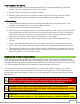
MONITOR AND NOZZLE HYDRAULIC DATA Interpreting Flow Data The following graphs offer the pressure losses for the monitor (and other devices) in terms of Total Static Pressure Drop. This Total Static Pressure Drop can be found by measuring the difference between the static inlet pressure and the static outlet pressure. The static pressure at either of these points can be found using a simple pressure gauge. An illustration of this method can be seen below.
Scorpion RF Monitor 8593-04 Copperhead RFLosses Losses 4.0" Outlet 3.0"Inlet Inletand and 3.5" 2.5" Outlet 60 50 Pressure (PSI) Pressure (PSI) 40 30 20 10 0 0 200 400 600 800 1000 1200 1400 1600 1800 2000 FlowRate Rate (GPM) (GPM) Flow Total Static Pressure Drop CATALOG NO. SM-1250BE INLET SIZE STREAM SETTING 3.5 SS NARROW FOG WIDE FOG Friction Loss NOZZLE DISCHARGE U.S.
IF YOU CAN SEE THIS TEXT, PLEASE REPRINT THIS PAGE AT 100% (NOT SCALED) FROM THE DIGITAL PDF. DOUBLE CHECK BEFORE DRILLING. IF YOU CAN SEE THIS TEXT, PLEASE REPRINT THIS PAGE AT 100% (NOT SCALED) FROM THE DIGITAL PDF. DOUBLE CHECK BEFORE DRILLING. COMPONENT MOUNTING TEMPLATES NOTE: Pages must NOT be scaled during printing or template size will be scaled incorrectly.
0.55 4.92 4.45 0.24 0.281-DRILL THRU 2-HLS. REQ'D. 21 IF YOU CAN SEE THIS TEXT, PLEASE REPRINT THIS PAGE AT 100% (NOT SCALED) FROM THE DIGITAL PDF. DOUBLE CHECK BEFORE DRILLING. 2.05 3.15 IF YOU CAN SEE THIS TEXT, PLEASE REPRINT THIS PAGE AT 100% (NOT SCALED) FROM THE DIGITAL PDF. DOUBLE CHECK BEFORE DRILLING.
Auxiliary Battery Mounting Layout THIS IS NOT A TEMPLATE 22
ELKHART BRASS 1302 WEST BEARDSLEY AVE P.O. BOX 1127 ELKHART, IN 46514 PHONE: 1-574-295-8330 • 1-800-346-0250 FAX: 574-293-9914 WWW.ELKHARTBRASS.COM © ELKHART BRASS MFG. CO., INC. 2014 8593-04 MONITORS INSTALLATION, OPERATION, AND MAINTENANCE INSTRUCTIONS 98520000 REV.