7200 EXM Monitor Installation, Operating, & Maintenance Instructions PHYSICAL: 1302 WEST BEARDSLEY AVE • ELKHART, IN 46514 • WWW.ELKHARTBRASS.COM MAILING: P.O. BOX 1127 • ELKHART, IN 46515 • 1-574-295-8330 • 1-800-346-0250 © 2014 ELKHART BRASS MFG. CO., INC.
TABLE OF CONTENTS PRODUCT SAFETY INFORMATION 3 MONITOR CALLOUT DRAWING 4 SYSTEM COMPONENTS 5 INSTALLATION INSTRUCTIONS 9 Installation Step 1: Mount and Wire all System Components 10 Installation Step 2: Configure the EXM System 18 Installation Step 3: Calibrate the EXM System 19 Installation Step 4: Check Installation 21 OPERATING INSTRUCTIONS 22 MAINTENANCE INSTRUCTIONS 30 SYSTEM SPECIFICATIONS 32 MONITOR AND NOZZLE HYDRAULIC DATA 36 COMPONENT MOUNTING TEMPLATES 38 To view the mos
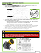
PRODUCT SAFETY INFORMATION All personnel who may be expected to use this equipment must be thoroughly trained in its safe and proper use. Before flowing water from this device, check that all personnel (fire service and civilian) are out of the stream path. Also, check to make sure stream direction will not cause avoidable property damage. Become thoroughly familiar with the hydraulic characteristics of this equipment, and the pumping system used to supply it.
MONITOR CALLOUT DRAWING X-Stream Series Master Stream Nozzle Double Race Bearings 2.
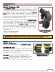
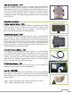
SYSTEM COMPONENTS MONITOR Monitor – 7200 The monitor is specially designed to be compact providing a greatly reduced swing radius. Unique waterway swivel joints utilize stainless steel thrust rods, and needle roller thrust bearings, for unprecedented durability in a range of applications. The utilizes a cast vaned waterway to minimize large-scale turbulence. The monitor can be controlled by hardwired input devices via CAN bus or by an optional upgraded Radio Frequency (RF) device.
CONTROL Joystick Controller - 7030 The Joystick Controller must be used in conjunction with the 7070 OEM Interface Module (Joystick and OEM Interface Module can be ordered together as the 7035 package). The Joystick Controller can be mounted inside the apparatus cab to control all monitor functions, including oscillation. The monitor direction (both vertical and horizontal movement) is changed by moving the joystick in the desired direction of travel.
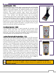
OEM Interface Module - 7070 The OEM Interface Module is used in conjunction with either the Elkhart Brass or customer supplied joystick, or OEM installed switches. The OEM Interface Module may be configured to handle switching power or ground. The Interface Module provides the option of mounting a joystick or switches in the apparatus cab to control all monitor functions, including oscillation. The OEM Interface Module may be powered with 12 or 24 Volts.
CAN Connector Kit - 37221000 This kit provides the wired connectors needed to branch off the main CAN communication line, and allows you to connect another EXM component between the two EXM components at the ends of the main line. One kit is needed for each additional EXM component that is added to the main CAN line. VALVE Unibody Valve with E3F Electric Actuator The water valve kit provides a convenient remote on/off and preset valve positioning control of the water supply to the .
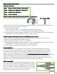
INSTALLATION INSTRUCTIONS Installation Overview: Step 1 – Mount and Wire All System Components Step 2 – Configure the EXM System (If Required) Step 3 – Calibrate the EXM System Step 4 – Check Installation Recommended electrical requirements for Power and Ground wire gauge and length: monitor: Distance Ft.(m) 100(30.5) – 150(45.7) 50(15.2) < 100(30.5) 25(7.62) < 50(15.2) < 25(7.
Installation Step 1: Mount and Wire All System Components Monitor – Before mounting the monitor, ensure that space allows for monitor to be rotated and calibrated. Disconnect all electrical connections. Mount the monitor onto base: o Flanged Base – Mount the monitor onto an appropriate flatface flange with 5/8-11 UNC grade 5, carbon steel or stainless steel bolts & nuts (3” flange or DN80-PN16: 4 bolts, 4” flange: 8 bolts).
Proximity Sensor for Extended Travel – An OEM supplied proximity sensor is used only for extended travel functionality, and is not necessary for standard monitor operation. The Cobra EXM is capable of vertical extended travel beyond the calibration point (straight up). An additional ground input is needed to enable this functionality. This functionality is intended to allow an OEM supplied proximity sensor to be used to enable or disable extended travel when the monitor is used with aerial applications.
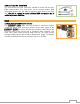
If the Panel Mount will use RF communication, install the RF Transceiver Module into the controller. o Remove the back cover from the Panel Mount Controller using a flathead screwdriver. o Connect the RF Transceiver with the wires running the length of the board as shown in the picture to the right. o Reattach the back cover of the Panel Mount. Ensure no wires are pinched. o If the CAN leads will not be used, replace wires with appropriate plugs.
Converting the Panel Mount Controller into a Handheld Controller – (Using Handheld Conversion Kit) Handheld Conversion Kit will include Battery Pack, Docking Station, and all hardware. Install a RF Transceiver Module into the back of the Panel Mount Controller as instructed in the Panel Mount installation section. Connect Battery Pack plugs to the Panel Mount Controller as shown. The CAN connector will not be used and should be placed inside the Battery Pack as shown.
2 1 OEM Interface Module Plug Information Joystick Plug Information Valve Plug If the 7070 OEM Interface Module will use RF communication, install the RF Transceiver Module as described in the following steps. o Remove the cover from the OEM Interface Module using a Phillips screwdriver. o Connect the RF Transceiver with the wires running the length of the board as shown here.
Position Feedback Display – Using the Position Display template shown in the Component Mounting Templates section, drill the two 11/64” holes shown through the panel intended for mounting the display. Mount the Position Feedback Display using two (2) 6-32 x ½” fasteners secured with blue Loctite 242 or equivalent. Torque to 50-60 in-lbs. 1 Connect plug 2 leads to the appropriate CAN line. Supply power to the Position Feedback Display by connecting plug 1 leads to an appropriate power source.
EXM CAN Stow Module – Using the EXM CAN Stow Module template shown in the Component Mounting Templates section, drill the two (2) 1/4” dia. holes through the surface intended for mounting. Mount the Stow Module using two (2) 1/4” dia. fasteners secured with blue Loctite 242 or equivalent. Connect Plug 2 leads to the appropriate CAN line.
Electric Actuated Unibody Valve – Install the valve into the water supply line. Supply power to the valve by connecting the red and black leads coming from the valve plug to an appropriate power source. Using the black, green, and blue leads from the plug, connect the valve to the appropriate CAN line. Supply power to the valve actuator by connecting the actuator plugs. Install a 30 Amp fuse to the positive power lead of the valve for a 12V system (15 Amp for 24V system).
Installation Step 2: Configure the EXM System NOTE: EXM systems using CAN communication and consisting of a monitor and one controller (panel mount or OEM interface) do not require configuration. EXM monitors and controllers come factory set for CAN termination. A position feedback display can also be used without the need for configuration; as long as it is connected to the main CAN line (see CAN connector kit) between the monitor & controller.
Installation Step 3: Calibrate the EXM System After successfully configuring the system, the system must be calibrated. Calibrating the EXM system’s horizontal and vertical rotation is a necessary step for EXM systems of all types. To view a demonstration of system calibration and entering setup commands go to www.elkhartbrass.com to download the appropriate EXM System Instructional Video. Setup Mode Before the EXM system can be calibrated, the system must be put into Setup Mode.
Calibrating Vertical Rotation - The Vertical calibration point is factory set at 90° (straight up). This is the position needed when wiring for extended travel (see Operating Instructions E), or when using a Position Feedback Display. This calibration will establish the highest vertical travel point of the monitor and allow rotation in the downward direction the total range specified during system calibration.
Installation Step 4: Check Installation After mounting, wiring, configuring, and calibrating the EXM system, check the installation of the entire EXM system. Ensure that all components have been mounted securely and have had the correct fuses installed within their wiring leads. Ensure that all components have been configured (if required) and that all components are functioning. Ensure that the EXM system has been calibrated correctly for its specific installation.
OPERATING INSTRUCTIONS To view a demonstration of some operating commands go to www.elkhartbrass.com to download the appropriate EXM System Instructional Videos. A.
C. Re-calibrating Horizontal and Vertical Rotation Calibrating the EXM system’s horizontal and vertical rotation is a necessary step for EXM systems of all types. The calibration points serve as a starting point for all other motion limits and commands entered to the EXM system. If not properly calibrated, the system may not operate correctly.
E. Extended Travel The Cobra EXM’s maximum vertical travel is now dependent (as of firmware 2.0.56) on the state of an additional input to position 3 of the 6-pin monitor power connector. This input allows the attachment of an OEM provided proximity sensor to trigger an open or grounded state of operation. The discharge vertical rotation limits from the horizontal center line (discharge parallel to the ground) for the proximity sensor input state are shown in the table below.
o Hold the PRESET button, then press the OPEN button, and then release both. o When the EXM system is taken out of Setup Mode, the monitor will be prevented from moving below and to the right of this point.
H. Motor Speed The speed of both the horizontal and vertical motors can be changed from something different than that set during configuration of the EXM system. The monitor’s horizontal and vertical motors can be set to either Fast or Slow in one of four combinations.
Pressing UP, DOWN, LEFT, RIGHT, or OSCILLATE will stop oscillation of a boxed area (Pressing LEFT, RIGHT, or OSCILLATE will stop horizontal oscillation while pressing UP, DOWN, or OSCILLATE will stop vertical oscillation. o All other functions can be operated without stopping oscillation. K. Handheld Controller Sleep / Hibernation Mode Sleep Mode – The Handheld Controller will go into sleep mode after one minute of inactivity. The blue power LED will blink every three seconds while in sleep mode.
N. Write Diagnostic File Power up all EXM system components. Remove the USB cover from any input controller. (If the system has more than one controller select the one with the easiest access. See illustration below for locations of the USB connection) Handheld & Panel Mount - Remove the top cover on the controller with a phillips screwdriver. OEM Interface Module - Remove the cover with a phillips screwdriver to locate the USB port.
Press and release the PRESET button The input controller will read the hex file on the flash drive and install it as long as the copied firmware is newer than the existing firmware. o This process will likely take up to ten minutes to complete. If using an RF input controller, update time may be up to three times as long.
MAINTENANCE INSTRUCTIONS Preventive Maintenance The complete monitor and control system should be inspected during each apparatus check. Careful inspection for damage to the monitor, valve or nozzle is especially important after use of the monitor in emergency operations.
o The close LED will flash while the valve is closing whether in auto-travel mode or while holding the CLOSE button. The CLOSE button LED will stay lit while the valve is in the closed position unless the user brings the system into Setup or Programming Modes. o The preset LED will flash after the PRESET button has been pressed and will continue to flash until the preset destination is reached.
SYSTEM SPECIFICATIONS 7200 EXM Monitor Max Flow Rating Max Operating Pressure Inlet Size Outlet Size Travel Movement Swing Radius Stow Height Weight Operating temperature range Environmental Rating Monitor Controller Input power Control Communication Electrical Load Fuse Rating RF power output Operating temperature range Environmental Rating FCC ID Motor (12 VDC) Run Current Stall Current Current Trip Point Motor (12 VDC) Run Current Stall Current Current Trip Po
RF power output Transmitter dimensions Transmitter weight Operating temperature range Environmental Rating FCC ID Handheld Controller - 7015 Input power Expected battery life Real time clock & calendar (RTCC) battery life Electrical Load Fuse Rating RF power output Transmitter dimensions Transmitter weight Operating temperature range Environmental Rating FCC ID Meets FCC part 15 requirements for license free operation (Output if applicable) 7 17/32” x 3 19/32” X 1 1/8”
J1939 CAN Communication Structure Preliminary Configuration for Input Control CAN Settings: J1939_SOURCE_ADDRESS address range for monitors = 0x80-9F, 0xF0-0xF1 (18 monitors supported on a single CAN network, 0xF0 and 0xF1 are reserved) J1939_SOURCE_ADDRESS address range for extenders = 0xD0-DF J1939_SOURCE_ADDRESS address range for input controls = 0xA0-0xBF, 0x0C (0x0C is reserved) J1939_SOURCE_ADDRESS address range for display boards = 0xC0-CB J1939_SOURCE_ADDRESS address range for CAN Stow Modules = 0xC
Monitor Position Feedback Message Repetition rate: 100mS Data Length: 8 Extended Data Page: 0 Data Page: 0 PDU Format: 255 PDU Specific: 240 Default Priority: 6 Parameter Group Number: 255,240 (0x00FFF0) – broadcast message Start Position Length Parameter 0 1 byte 0xFD – Command 1 2 bytes Horizontal Position Feedback (0000-3600) 0000 corresponds to the left most allowable operating position.
MONITOR AND NOZZLE HYDRAULIC DATA Interpreting Flow Data The following graphs offer the pressure losses for the monitor (and other devices) in terms of Total Static Pressure Drop. This Total Static Pressure Drop can be found by measuring the difference between the static inlet pressure and the static outlet pressure. The static pressure at either of these points can be found using a simple pressure gauge. An illustration of this method can be seen below.
Pressure (PSI) 7200 Cobra EXM Static Pressure Drop (3” Inlet and 2.5” Outlet) Flow (GPM) Total Static Pressure Drop CATALOG NO. INLET SIZE SM-1000E 2.5 SM-1250E 2.5 STREAM SETTING SS NARROW FOG WIDE FOG SS NARROW FOG WIDE FOG Friction Loss NOZZLE DISCHARGE U.S.
IF YOU CAN SEE THIS TEXT, PLEASE REPRINT THIS PAGE AT 100% (NOT SCALED) FROM THE DIGITAL PDF. DOUBLE CHECK BEFORE DRILLING. IF YOU CAN SEE THIS TEXT, PLEASE REPRINT THIS PAGE AT 100% (NOT SCALED) FROM THE DIGITAL PDF. DOUBLE CHECK BEFORE DRILLING. COMPONENT MOUNTING TEMPLATES NOTE: Pages must NOT be scaled during printing or template size will be scaled incorrectly.
IF YOU CAN SEE THIS TEXT, PLEASE REPRINT THIS PAGE AT 100% (NOT SCALED) FROM THE DIGITAL PDF. DOUBLE CHECK BEFORE DRILLING. Position Display Indicator Mounting Template IF YOU CAN SEE THIS TEXT, PLEASE REPRINT THIS PAGE AT 100% (NOT SCALED) FROM THE DIGITAL PDF. DOUBLE CHECK BEFORE DRILLING.
IF YOU CAN SEE THIS TEXT, PLEASE REPRINT THIS PAGE AT 100% (NOT SCALED) FROM THE DIGITAL PDF. DOUBLE CHECK BEFORE DRILLING. IF YOU CAN SEE THIS TEXT, PLEASE REPRINT THIS PAGE AT 100% (NOT SCALED) FROM THE DIGITAL PDF. DOUBLE CHECK BEFORE DRILLING.
IF YOU CAN SEE THIS TEXT, PLEASE REPRINT THIS PAGE AT 100% (NOT SCALED) FROM THE DIGITAL PDF. DOUBLE CHECK BEFORE DRILLING. IF YOU CAN SEE THIS TEXT, PLEASE REPRINT THIS PAGE AT 100% (NOT SCALED) FROM THE DIGITAL PDF. DOUBLE CHECK BEFORE DRILLING.
ELKHART BRASS PHYSICAL: 1302 WEST BEARDSLEY AVE • ELKHART, IN 46514 MAILING: P.O. BOX 1127 • ELKHART, IN 46515 PHONE: 1-574-295-8330 • 1-800-346-0250 FAX: 1-574-293-9914 WWW.ELKHARTBRASS.COM © ELKHART BRASS MFG. CO., INC. 2014 7200 EXM MONITOR INSTALLATION, OPERATION, AND MAINTENANCE INSTRUCTIONS 98491000 REV.