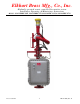
Elkhart Brass Mfg., Co., Inc. Hydraulic operated remote controlled fire monitor system Installation, Operating, & Maintenance Instructions Models: 294-11XBHC-N4X, 294-11XBHC-N7/4, 299-20XHC-N4X, & 299-20XHC-N7/4 Revised 8/20/2010 1 EB98175000_Rev.
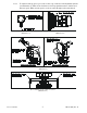
INSTALLATION INSTRUCTIONS 1.0 Installing Monitor and Nozzle: 1.1 1.2 1.3 1.4 Bolt the monitor to standpipe, terminated with 4" - 150# Flat Face ASA flange base. Standpipe must be structurally strong enough to withstand reaction force of nozzle when discharging a straight stream at 90º of the standpipe or tower. The formula for calculating nozzle reaction is: REACTION FORCE = 0.0505 x G.P.M. x √¯P.S.I. Inlet pressure at base of monitor must be high enough to allow for pressure Lose through monitor.
2.0 Electrical control system installation: 2.1 Install control boxes at designated locations and cut out holes in box to attach conduit. All cable entry knockouts on all NEMA #4X enclosures are provided by others. All NEMA #7/4 enclosures have N.P.T. female threaded entries provided. 2.2 Install conduit and pull electrical conductors between control boxes and Valve & Pump Box. Main power source to be connected at Valve & Pump Box, supplied by others.
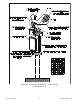
3.3.6 Disconnect hydraulic lines from horizontal actuator ports V2A & V2B. Open port control valves at both ends of rotary actuator, turn screws counterclockwise until they stop. (See illustrations 1 & 4 for location). Manually turn monitor to maximum horizontal clockwise position. 3.3.7 Insert open end of V2A hydraulic hose into clean container, and activate “LEFT” mode switch at control box. Hold switch until hydraulic fluid is discharging from hose and is free of air.
3.5.6 To adjust nozzle tip speed, port control valve is provided in nozzle hydraulic cylinder (see illustration 2). Turn screw clockwise to slow tip speed down and c’clockwise to increase speed. When nozzle speed is set, flow water through nozzle and recheck.
Monitor & Nozzle hydraulic connections (Illustration 5) Revised 8/20/2010 6 EB98175000_Rev.
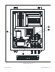
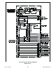
Valve & Pump Box Interior (Illustration 6) Revised 8/20/2010 7 EB98175000_Rev.
OPERATING INSTRUCTIONS 5.0 Monitor control function operation 5.1 Manual control operation: “SYSTEM ON” push button switch will turn on power to all control circuits and can be activated at any control box. This will enable all monitor controls. “SYSTEM STANDBY” push button switch will disconnect power from all monitor functions at any control panel. Water valve “OPEN” & “CLOSE” push button switches are momentary contact switches that operate a latching relay in Valve & Pump Box.
MAINTENANCE INSTRUCTIONS 6.0 Maintenance on monitor system 6.1 Monthly inspection and maintenance: 6.1.1 Check all indicator lights and replace bulbs if not operatable. 6.1.2 Check hydraulic pump reservoir for fluid level. 6.1.3 Operate all functions on system to insure proper working condition. 6.1.4 Operate all monitor and nozzle functions several times, to activate solenoid valves in Valve & Pump Box. This will clean any residue from spools and keep them from sticking. 6.
Valve & Pump Box Electrical Diagram (Illustration 7) Revised 8/20/2010 10 EB98175000_Rev.
Hydraulic Schematic (Illustration 8) Revised 8/20/2010 11 EB98175000_Rev.
Elkhart Brass Mfg. Co. Inc. E l kha r t , I n d i a n a , U S A Shipping address 1302 West Beardsley Ave. Elkhart, Indiana 46514 Mailing address P.O. Box 1127 Elkhart, Indiana 46515 Phone: (574) 295-8330 (800) 346-0250 Fax: (574) 293-9914 Web Site: www.elkhartbrass.com e-mail: info@elkhartbrass.com Revised 8/20/2010 12 EB98175000_Rev.