
User's Manual


M1 Installation and Programming Manual
Page 7
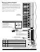
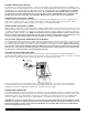
(Right Side Terminals)
OUT1
+12V (+VAUX)
NEG
16
15
14
13
12
11
10
9
8
7
NEG -
DATA B
+12V
DATA BUS
-
A
B
C
J3 J4
1 WAY
PLC
Mode
2 WAY
JP2
RS232
+
J16
J5
OUT3 LED
OUT3OUT2
+
-
+
-
+VKP
DATA B
DATA A
NEG
Not Used
R1
TIP
RING
T1
* See Auxiliary Current ratings
1 WAY (PL513/PSC04)
Select PLC Mode (JP2)
Selects single or bi-directional
PLC Transmissions
2 WAY (TW523/PSC05)
JP2
Siren
Voice
+
-
+
-
TELCO
LINE
HOUSE
PHONES
OUTPUTS
AUDIO NETWORK INTERFACE
J7
Aux Data Bus (J3)
For wireless receiver. Presently
works with ITI / Caddx NX408E,
NX416E, or NX448E. See
Programming Menu 14.
Audio Network Connection (J7)
For Two-Way Listen-in and Future Use!
J1J2
NEG
+12V
N/CCOMN/O
Compiles with FCC Part 68
Reg. Number: US:5K6AL03BELK-M1
Ringer Equivalence REN: 0.3B
Use USOC RJ-31X connector.
Complies with the limits for class B computer
devices in accordance with the specifications of
subpart J of part 15 of FCC rules.
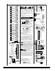
Out 3 - Programmable General Purpose Relay
Rated at 5Amps @ 12 - 28VDC
(Dry Contacts)
Terminating Jumper (JP3): See
important information about Data
Bus Termination.
This former earth ground terminal is no longer used. Do NOT connect this terminal or any neg. terminal to earth ground.
Out 1 - Voice/Siren
Speaker output only (Interior)
Out 2 - Siren or Voltage
Selectable as Siren Driver (20 Watts) OR Voltage (open
collector-switch to ground protected by 1.25Amp PTC).
Programmable Outputs (J16)
OUT 7 - 16 are +12V switched positive
general purpose outputs rated at 50mA.
Lighting
Interface Conn.
T
R
T1
R1
RJ31X JACK
(ELK-RJSET)
PC
Personal Computer
(Windows Based)
Serial Port (J4)
for Computer/ELKRP
(This connection not
evaluated by UL)
Lighting Interface Conn. (J5)
Use Std. 4 conductor modular telephone
cable to connect to a powerline Interface
(PSC05, X-10 PLC or equiv.).
Do not connect to a live phone line!
(This connection not evaluated by UL)
N/C
COM
N/O
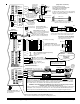
DATA BUS TERMINATION IS VERY IMPORTANT!!
Diagram shows 2 basic (4-wire) home run cables with daisy chained devices on each. Last device on each cable
MUST have a Terminating Jumper installed. Jumpers are marked JP2 on keypads, JP1 on Expanders. Control
Hardware pack has two black jumpers for this purpose. Jumpers engage a 120 Ohm resistor across data A & B
lines. NOTE: If there is only 1 data bus cable, install JP3 Jumper on the Control.
Temporary Connection "Plug-in" jacks for RS-485 Data Bus (J1 & J2)
Local connection for Data Bus Devices ie: Keypads, etc. for testing purposes only.
5
4
8
1
Tip
Ring
Green
Red
Yellow
Black
Demark
Block
ELK-SP30 or equiv.
ELK-SP35 or equiv.
PSC05 or
equiv.
Relay Expansion Module (ELK-M1RB)
Optional module adds 8 general purpose
relays. Plugs into J16 connector.
Input Expander:
ELK-M1XIN
16 additional zones
Output Expanders:
ELK-M1XOV ELK-M1OVR
16 voltage outputs 8 voltage & 8 relays
Red
Black
White
Green
Brown
Blue
Yellow
Violet
Pink
Tan
Orange
Grey
+VAUX
NEG
OUT 16
OUT 15
OUT 14
OUT 13
OUT 12
OUT 11
OUT 10
OUT 9
OUT 8
OUT 7
+12V
NEG
splice
Green
Grey
Red
Brown
ELK-M1KP
BLACK
WHITE
GREEN
JP3
RS-485 Data Bus Max. length is 4000 ft. Max.
devices vary by control. +VKP protected with 1.25A PTC
NOTE: If you want to home run more than 2 cables, run 6 or 8 conductor cable so that the data lines A & B can have
a return path to series connect back out to the next device. This is best done with a ELK-M1DBH Data Bus Hub
which accepts Cat5 or Cat6 cable with RJ45 plugs. For more information see diagram in keypad instructions.
WARNING! The RS485 Data Bus must NEVER have more that two (2) terminating jumpers installed.
Reliability, response, and behavior will be affected!
RS-485 DATA BUS
DATA A
RED
ELK-M1XIN
ELK-M1XOV
Jumper
Terminate
these two
devices.
DO NOT Jumper
Terminate these devices.
Keypad 1
ELK-M1KP
Keypad 2
ELK-M1KP
Keypad 3
Yellow
Green
Red
Black
Yellow
Green
Red
Black
Close up view of std. 4 conductor modular phone cord. When
viewed as shown (back to back), the pin to pin color coding
does not reverse. Cord for PLC must be similar to above.
End
view
11
Pin 2 < to > 2
Pin 3 < to > 3
Pin 5 < to > 5
Pinout for Serial Port Cable (9 pin male to 9 pin female)
Maximum recommended length = 50 ft.
Out 2 is supervised. If not used,
install a resistor (2.2k Ohm) to
avoid Output 2 trouble condition.