
User's Manual


M1 Installation and Programming Manual
Page 12
NEG -
DATA B
+12V
DATA BUS
+VKP
DATA B
DATA A
NEG
EGND
J1J2
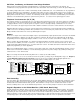
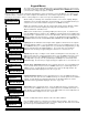
RE: Data Bus Termination Note
DATA BUS TERMINATION IS VERY IMPORTANT!!
Ideal setup is 2 home run cables (4 wire) with daisy chained devices along each. The last device on each cable MUST have
a Terminating resistor installed (activated) via the gold 2 pin header/jumpers marked JP2 on keypads, JP1 on expanders.
Place a black shorting cap (see hardware pack) onto the 2 gold pins to install a 120 Ohm resistor across data lines A & B.
NOTE: Place a shorting cap on JP3 of Main Board it there is only 1 data bus cable. See diagrams on multiple cables.
Temporary Connection "Plug-in" jacks for RS-485 Data Bus (J1 & J2)
Local connection for Data Bus Devices ie: Keypads, etc. for testing purposes only.
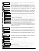
ELK-M1KP
BLACK
WHITE
GREEN
JP3 Teminating Jumper
(Located beneath cover)
RS-485 Data Bus (Max. length is 4000 ft.
Max. bus devices vary by control.)
WARNING! The RS485 Data Bus must NEVER have more that two (2) terminating resistors
header/jumpers installed. Reliability and response will be negatively affected!
RS-485 DATA BUS
DATA A
RED
ELK-M1XIN
ELK-M1XOV
Jumper
Terminate
these two
devices.
DO NOT Jumper
Terminate these devices.
Keypad 1
ELK-M1KP
Keypad 2
ELK-M1KP
Keypad 3
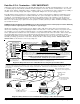
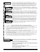
If home running 3 or more cables, use 6 conductor cables. At the device, make a three way splice of the data A wire, device A wire or terminal, and a
return data A1 wire (using one of the extra wires). Do the same for the data B wire. At the control, make a two way splice of the data A1 return wire (series
connection) to the outgoing data A wire of the next cable. Repeat for the data B wire. Terminate at the last device and the control JP3 ONLY!
Keypad
Keypad
Keypad
Install Teminating Jumper
Cap on this last device AND
on the control JP3.
6
c
o
n
d
u
c
t
o
r
c
a
b
l
e
s
+VKP
DATA A
DATA B
NEG
DATA
A1 A
B1 B
DATA
A1 A
B1 B
DATA
A1 A
B1 B
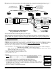
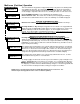
WHITE
GREEN
BLACK
RED
A
-
+
B
SPARE
PAIR
See Diagram on next page for connection
of Optional Output and Zone Input
WHITE
GREEN
BLACK (-)
RED +12
BLUE
BROWN
6
Conductor
Cable
Keypad
DATA
A1
B1
For future
devices
A
1
B1
Diagram for Daisy Chain Connection of Data Bus Devices Using Two (2) Home Run Cables
Connect each device to the 6
conductor cable as shown.
Diagram for Daisy Chain Connection of Data Bus Devices Using 3 or More Home Run Cables.
NOTE: The power wires are parallel
connected to the +VKP & Neg terminals.
RS-485 DATA BUS
Data Bus E.O.L. Termination - VERY IMPORTANT!
Unlike many controls, the M1 features a true RS-485 “differential” data bus operating at 38,400 baud (bits per second). This
is a relatively high speed by industry standards and was designed to ensure fast, accurate communications. As a result of
this high speed, data bus terminating resistors (120 Ohm resistors) are recommended in order to eliminate the possibility of
reflection errors caused by varying cable lengths, especially with multiple home run (star topology) cables.
Every M1 data bus device; keypad, zone, output expander, etc. and the control board has a built-in bus terminating resistor
(120 Ohm). Each terminating resistor is installed (activated) via a 2 pin header/jumper (2 Gold Pins) using a small black
shorting cap. The terminating resistors are marked JP2 on the keypads and JP1 on the expanders. From the factory, no
terminating resistors are installed (activated). The control hardware pack includes two of the small black shorting caps.
When one of the shorting caps is placed on the two gold pins, it installs (activates) the built-in 120 Ohm terminating resistor
across Data Lines A & B.
WARNING! The RS-485 Data Bus must NEVER have more than 2 terminating resistors header/jumpers installed. Reliability
and response will be negatively affected. See diagrams on opposite page.
Ideally, there should be no more than two home run data bus cables, with devices daisy chain connected along the two
cables and a terminating resistor (header/jumper) installed on the last device of each cable. However, if you prefer to home
run everything (3 or more), we highly recommend using 6 or 8 conductor cabling (CAT5 or CAT6 cable is ideal). At each
device, splice data wires A & B to 2 of the extra conductors so they return back to the control as A1 & B1. At the control, splice
the returning data wires A1 & B1 in series to data wires A & B going back out to the next device. Remember to install a
terminating header/jumper on the last wired device. Electrically the data wires are now in one long series circuit. Connect
the POS (+) and Neg (-) power wires of each device directly to the M1’s +VKP and Neg terminals. DO NOT SERIES THE
POWER WIRES as this will cause unnecessary voltage loss.