Preface Copyright This publication, including all photographs, illustrations and software, is protected under international copyright laws, with all rights reserved. Neither this manual, nor any of the material contained herein, may be reproduced without written consent of the author. Version 1.0 Disclaimer The information in this document is subject to change without notice.
Declaration of Conformity This device complies with part 15 of the FCC rules. Operation is subject to the following conditions: • This device may not cause harmful interference. • This device must accept any interference received, including interference that may cause undesired operation.
About the Manual The manual consists of the following: Chapter 1 Introducing the Motherboard Describes features of the page 1 motherboard. Chapter 2 Installing the Motherboard Describes installation of page 9 motherboard components. Chapter 3 Using BIOS Provides information on us- page 29 ing the BIOS Setup Utility. Chapter 4 Describes the motherboard page 71 Using the Motherboard Software software.
Memo iv Z87H3-AX EXTREME (GOLDEN) USER MANUAL
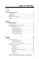
TABLE OF CONTENTS Preface i Chapter 1 1 Introducing the Motherboard 1 Introduction...................................................................................1 Pakage Contents............................................................................1 Specifications................................................................................2 Motherboard Components..........................................................4 I/O Ports.............................................................
Chapter 4 71 Using the Motherboard Software 71 Auto-installing under Windows 7/8............................................71 Running Setup.........................................................................71 Manual Installation..........................................................................73 ECS Utility Software (Intelligent EZ Utility).....................................73 Chapter 5 77 TM ATI CrossFire Technology Support 77 Requirements..............................................
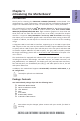
Introduction Thank you for choosing the Z87H3-AX EXTREME (GOLDEN)* motherboard. This motherboard is a high performance, enhanced function motherboard designed to support the LGA1150 socket for Intel® 4th Generation CoreTM Family Processors. Chapter 1 Chapter 1 Introducing the Motherboard This motherboard is based on Intel® Z87 Express Chipset for best desktop platform solution. It supports up to 32 GB of system memory with dual channel DDR3 3000+(OC)/2133/1866/1600/1333 MHz.
Chapter 1 Specifications CPU • • LGA1150 socket for Intel ® 4 th Generation Core TM Family Processors TDP: 200W Note: Please go to ECS website for the latest CPU support list. Chipset • Intel® Z87 Chipset Extra Chipset • • 1 x ASM1061 Chip integrates one eSATA 6Gb/s Host Controller 2 x ASM1074 Chips supports the four USB 3.0 poers at the rear I/O, and the three Front USB 3.0 headers are from Z87.
• • • • • • • • • • • • • • • • • • • • • • • 1 x 24-pin ATX Power supply connector 1 x 8-pin ATX Power supply connector 1 x 4-pin CPU_FAN connector 1 x 4-pin SYS_FAN connector 1 x 3-pin PWR_FAN connector 1 x 3-pin NB_FAN connector 2 x USB 2.0 headers support additional four USB 2.0 ports (F_USB1 supports EZ charger function) 3 x USB 3.0 headers support additional six USB 3.
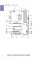
Chapter 1 4 Motherboard Components Z87H3-AX EXTREME (GOLDEN) USER MANUAL
LABEL 1. CPU Socket 2. CPU_FAN 3. DDR3_1~4 4. EZM1 5. ATX_POWER 6. RST_BTN 7. PWR_BTN 8. NB_FAN1 9. BZ 10. POST 11. 80P_SW 12. SATA3_1~6 13. QUICK_OC 14. CASE 15. BIOS_SET 16. ME_UNCLOCK 17. F_PANEL 18. USB3F1~3 19. F_USB1~2 20. COM 21. F_AUDIO 22. PCIEX16_T 23. ROM_BACKUP 24. PCI 25. MINIPCIE 26. PCIEX16_3 27. PCIE1 28. PCIEX16_1~2 29. PWR_FAN 30. SYS_FAN 31.
Chapter 1 I/O Ports 1. Wireless LAN Dongle (WiFi) Use this port to receive wireless signal. 2. CLR_CMOS_BTN Use the CLR_CMOS button to clear CMOS. 3. Display Port (DP) You can connect the display device to the display port. 4. LAN Ports Connect an RJ-45 jack to the LAN port to connect your computer to the Network. LAN LED Activity LED Link LED Status Description OFF Orange blinking OFF Green No data Active No link Link Link LED LAN Port 5.
C: Rear Headphone B: Rear out & Line in D: Front/Stereo out - E: Mic/Line in The above port definition can be changed to audio input or audio output by changing the driver utility setting. Chapter 1 A: Center & Woofer 7. Optical SPIDF Output port This jack connects to external optical digital audio output devices. 8. USB 3.0 Ports Use the USB 3.0 ports to connect USB 3.0 devices. 9. HDMI Port You can connect the display device to the HDMI port. 10.
Chapter 1 8 Table of onboard Buttons Item name PCB mark EZ LED Display 80P_SW EZ Quick OC QUICK_OC EZ Enter BIOS BIOS_SET EZ Duo BIOS ROM_BACKUP EZ RESET RST_BTN EZ POWER EZ Clear CMOS PWR_BTN CLR_CMOS_BTN Function When this button collocates with the 7-segment display on the MB, it will display the following information about the MB, and it will switchover in the following order. 1. Post code 2. CPU TEMP 3. CPU VOLTAGE 4. CPU POWER 5.
Chapter 2 Installing the Motherboard 2-1. Safety Precautions • • • • Wear a grounding strap attached to a grounded device to avoid damage from static electricity. Discharge static electricity by touching the metal case of a safely grounded object before working on the motherboard. Leave components in the static-proof bags. Always remove the AC power by unplugging the power cord from the power outlet before installing or removing the motherboard or other hardware components.
2-4. Installing Hardware 2-4-1. Installing the Processor • • Chapter 2 • • This motherboard has an LGA1150 socket. When choosing a processor, consider the performance requirements of the system. Performance is based on the processor design, the clock speed and system bus frequency of the processor, and the quantity of internal cache memory and external cache memory. You may be able to change the settings in the system Setup Utility.
Chapter 2 D. Rotate the load plate onto the package IHS (Intergraded Heat Spreader). Engage the load lever while pressing down lightly onto the load plate. Secure the load lever with the hook under retention tab. Then the cover will flick automatically. Please save and replace the cover onto the CPU socket if processor is removed.
2-4-2. Installing the CPU Cooler • • • Chapter 2 • • • Install the cooling fan in a well-lit work area so that you can clearly see the motherboard and processor socket. Avoid using cooling fans with sharp edges in case the fan casing and the clips cause serious damage to the motherboard or its components. To achieve better airflow rates and heat dissipation, we suggest that you use a high quality fan with 3800 rpm at least.
• • • • This motherboard accommodates four memory modules. It can support four 240-pin DDR3 3000+(OC)/2133/1866/1600/1333 MHz. Do not remove any memory module from its antistatic packaging until you are ready to install it on the motherboard. Handle the modules only by their edges. Do not touch the components or metal parts. Always wear a grounding strap when you handle the modules. You must install at least one module in any of the four slots. Total memory capacity is 32 GB.
• The four DDR3 memory sockets (DDR3_1, DDR3_2, DDR3_3 and DDR3_4) are divided into two channels and each channel has two memory sockets as following: Channel A: DDR3_1, DDR3_2 Channel B: DDR3_3, DDR3_4 Chapter 2 Recommend memory configuration Model Sockets DDR3_1 DDR3_2 DDR3_3 DDR3_4 1 DIMM ~ Populated ~ ~ 1 DIMM ~ ~ ~ Populated 2 DIMMs ~ Populated ~ Populated 3 DIMMs Populated Populated ~ Populated 3 DIMMs ~ Populated Populated Populated 4 DIMMs Populated Populate
2-4-4. Installing Add-on Cards Chapter 2 The slots on this motherboard are designed to hold expansion cards and connect them to the system bus. Expansion slots are a means of adding or enhancing the motherboard’s features and capabilities. With these efficient facilities, you can increase the motherboard’s capabilities by adding hardware that performs tasks that are not part of the basic system.
Follow these instructions to install an add-on card: Chapter 2 1 Remove a blanking plate from the system case corresponding to the slot you are going to use. 2 Install the edge connector of the add-on card into the expansion slot. Ensure that the edge connector is correctly seated in the slot. 3 Secure the metal bracket of the card to the system case with a screw. 1.
2-4-5. Connecting Optional Devices Chapter 2 Refer to the following for information on connecting the motherboard’s optional devices: No. Components No. Components 1 EZM1 5 USB3F1~3 2 SATA3_1~6 6 F_USB1~2 3 CASE 7 COM 4 ME_UNLOCK 8 F_AUDIO 1. EZM1: Easy Measure Point Connector This connector allows user to measure the voltage easily.
2. SATA3_1~6 : Serial ATA Cconnectors SATA3_1~6 connectors support the Serial ATA 6Gb/s device. Simpler disk drive cabling and easier PC assembly. Chapter 2 3. CASE: Chassis Intrusion Detect Header This detects if the chassis cover has been removed. This function needs a chassis equipped with instrusion detection switch and needs to be enabled in BIOS.
Chapter 2 4. ME_UNLOCK: ME Unlock Header 5. USB3F_1~3: Front Panel USB 3.0 Headers This Motherboard implements three USB 3.0 header supporting six extra front USB 3.0 ports, which delivers 5Gb/s transfer rate. Please make sure that the USB cable has the same pin assignment as indicated above. A different pin assignment may cause damage or system hang-up.
6. F_USB1~2: Front Panel USB 2.0 Headers (F_USB1 supports EZ Charger) The motherboard has two USB 2.0 header supporting four USB 2.0 ports. Additionally, some computer cases have USB 2.0 ports at the front of the case. If you have this kind of case, use auxiliary USB 2.0 connector to connect the front-mounted ports to the motherboard. Chapter 2 F_USB1 supports EZ Charger technology, provides 3 times current than general USB port in off mode for USB devices.
7. COM: Onboard Serial Port Header Chapter 2 Connect a serial port extension bracket to this header to add a serial port to your system. 8. F_AUDIO: Front Panel Audio Header The front panel audio header allows the user to install auxiliary front-oriented microphone and line-out ports for easier access. This header supports HD audio by default.
2-4-6. Installing a SATA Hard Drive This section describes how to install a SATA Hard Drive. About SATA Connectors Chapter 2 Your motherboard features six SATA connectors supporting a total of six drives. SATA refers to Serial ATA (Advanced Technology Attachment) is the standard interface for the IDE hard drives which are currently used in most PCs. These connectors are well designed and will only fit in one orientation.
2-4-7. Connecting Case Components Chapter 2 After you have installed the motherboard into a case, you can begin connecting the motherboard components. Refer to the following: No. Components No.
1 & 3 & 6 & 7. CPU_FAN (CPU Cooling FAN Connector) & NB_FAN1 (North Bridge Cooling FAN Connector) & PWR_FAN (Power Cooling FAN Connector) & SYS_FAN (System Cooling FAN Connector) Chapter 2 Connect Connect Connect Connect the CPU cooling fan cable to CPU_FAN. the North Bridge cooling fan connector to NB_FAN1. the power cooling fan connector to PWR_FAN. the system cooling fan connector to SYS_FAN. Users please note that the fan connector supports the CPU cooling fan of 1.1A ~ 2.2A (26.4W max) at +12V.
2 & 5. ATX_POWER (ATX 24-pin Power Connector) & ATX12V (ATX 12V Power Connector) Chapter 2 Connect the standard power supply connector to ATX_POWER. Connect the auxiliary case power supply connector to ATX12V. Connecting 24-pin power cable The ATX 24-pin connector allows you to connect to ATX v2.x power supply. With ATX v2.x power supply, users please note that when installing 24-pin power cable, the latches of power cable and the ATX_POWER match perfectly.
Connecting 8-pin power cable The ATX12 power connector is used to provide power to the CPU. When installing 8-pin power cable, the latches of power cable and the ATX12V match perfectly. Chapter 2 8-pin power cable Connecting 4-pin power cable The ATX12V power connector is used to provide power to the CPU. When installing 4-pin power cable, the latches of power cable and the ATX12V match perfectly.
4. F_PANEL: Front Panel Header Chapter 2 The front panel header (F_PANEL) provides a standard set of switch and LED headers commonly found on ATX or Micro ATX cases. Refer to the table below for information: Hard Drive Activity LED Connecting pins 1 and 3 to a front panel mounted LED provides visual indication that data is being read from or written to the hard drive. For the LED to function properly, an IDE drive should be connected to the onboard IDE interface.
Memo Chapter 2 28 Z87H3-AX EXTREME (GOLDEN) USER MANUAL
Chapter 3 Using BIOS About the Setup Utility The BIOS (Basic Input and Output System) Setup Utility displays the system’s configuration status and provides you with options to set system parameters. The parameters are stored in battery-backed-up CMOS RAM that saves this information when the power is turned off. When the system is turned back on, the system is configured with the values you stored in CMOS.
Press the delete key to access BIOS Setup Utility. Chapter 3 Above image is for reference only, for details please refer to actual image. Resetting the Default CMOS Values When powering on for the first time, the POST screen may show a “CMOS Settings Wrong” message. This standard message will appear following a clear CMOS data at factory by the manufacturer. You simply need to Load Default Settings to reset the default CMOS values. Note: Changes to system hardware such as different CPU, memories, etc.
In this manual, default values are enclosed in parenthesis. Submenu items are denoted by an icon . The default BIOS setting for this motherboard apply for most conditions with optimum performance. We do not suggest users change the default values in the BIOS setup and take no responsibility to any damage caused by changing the BIOS settings. BIOS Navigation Keys The BIOS navigation keys are listed below: KEY FUNCTION Exits the current menu Scrolls through the items on a menu +/-Change Opt.
Main Menu This menu shows the information of BIOS and enables you to set the system language, date and time. Main Advanced Chipset M.I.B. X System Date System Time Security Exit Set the Time. Use Tab to switch between Time elements. BIOS Information System Language Boot English Wed 04/03/2013 00:12:00 Chapter 3 : Select Screen /Click: Select Item Enter/Dbl Click : Select +/- : Change Opt.
Advanced Menu The Advanced menu items allow you to change the settings for the CPU and other system. Advanced Chipset LAN Configuration PC Health Status Power Management Setup ACPI Settings CPU Configuration SATA Configuration USB Configuration Super IO Configuration Intel(R) Rapid Start Technology Intel(R) Smart Connect Technology Intel(R) Thunderbolt M.I.B. X Boot Security Exit LAN Configuration Parameters : Select Screen /Click: Select Item Enter/Dbl Click : Select +/- : Change Opt.
LAN Configuration The item in the menu shows the LAN-related information that the BIOS automatically detects. Main Advanced Chipset M.I.B. X Boot LAN Configuration Onboard LAN 1 Controller Onboard LAN 2 Controller Enabled Enabled Security Exit Enabled/Disabled Onboard LAN 1 Controller : Select Screen /Click: Select Item Chapter 3 Enter/Dbl Click : Select +/- : Change Opt.
PC Health Status On motherboards support hardware monitoring, this item lets you monitor the parameters for critical voltages, temperatures and fan speeds. Main Advanced PC Health Status Chipset M.I.B. X Boot Security Exit 49 33OC 3139 RPM 0 RPM 0 RPM 0 RPM 1.068V 1.526V 1.068V 1.493V TCC Activation Temperature (DTS) 100 : Select Screen /Click: Select Item Enter/Dbl Click : Select +/- : Change Opt.
Smart Fan Mode (Normal) This item allows you to select the fan mode (Normal, Quiet, Silent, or Manual) for a better operation environment. If you choose Normal mode, the fan speed will be auto adjusted depending on the CPU temperature. If you choose Quite mode, the fan speed will be auto minimized for quiet environment. If you choose Silent mode, the fan speed will be auto restricted to make system more quietly. If you choose Manual mode, the fan speed will be adjust depending on users’ parameters.
Power Management Setup This page sets up some parameters for system power management operation. Advanced Chipset M.I.B. X Boot Exit About Resume by Ring Power Management Setup Resume By RING Resume By PME Resume By USB EUP Function Power LED Type Security Disabled Disabled Disabled Enabled Dual Color LED : Select Screen /Click: Select Item Enter/Dbl Click : Select +/- : Change Opt.
ACPI Settings The item in the menu shows the highest ACPI sleep state when the system enters suspend. Main Advanced Chipset M.I.B. X Boot ACPI Settings ACPI Sleep State S3 (Suspend to RAM) Security Exit Select the highest ACPI sleep state the system will enter when the SUSPEND button is pressed. : Select Screen Chapter 3 /Click: Select Item Enter/Dbl Click : Select +/- : Change Opt.
CPU Configuration The item in the menu shows the CPU. Advanced Chipset M.I.B. X Intel(R) Core(TM) i7-4770K CPU @ 3.
Limit CPUID Maximum (Disabled) Use this item to enable or disable the maximum CPUID value limit, you can enables this item to prevent the system from “rebooting” when trying to install Windows NT 4.0. Execute Disable Bit (Enabled) This item allows the processor to classify areas in memory by where application code can execute and where it cannot. When a malicious worm attempts to insert code in the buffer, the processor disables code execution, preventing damage or worm propagation.
SATA Configuration Use this item to show the mode of serial SATA configuration options. Advanced Chipset M.I.B. X Boot Security Exit Determines how SATA controller(s) operate.
USB Configuration Use this item to show the information of USB configuration. Main Advanced Chipset M.I.B. X Boot Security Exit USB Support Parameters USB Configuration All USB Devices Enabled Legacy USB Support Wi-Fi Enabled Enabled : Select Screen /Click: Select Item Chapter 3 Enter/Dbl Click : Select +/- : Change Opt.
Super IO Configuration Use this item to show the information of Super IO configuration. Advanced Chipset M.I.B. X Boot Security Exit Set Parameters of Serial Port 0 (COMA) Super IO Chip Serial Port 0 Configuration IT8732 : Select Screen /Click: Select Item Enter/Dbl Click : Select +/- : Change Opt.
Intel(R) Rapid Start Technology Use this item to show the information of Intel(R) Rapid Start Technology. Main Advanced Chipset Intel(R) Rapid Start Technology M.I.B. X Boot Disabled Security Exit Enable or disable Intel(R) Rapid Start Technology. Chapter 3 : Select Screen /Click: Select Item Enter/Dbl Click : Select +/- : Change Opt.
Intel(R) Smart Connect Technology Use this item to show the information of Intel(R) Smart Connect Technology. ISCT Support Advanced Chipset M.I.B. X Boot Disabled Security Exit Enable/Disable ISCT Support : Select Screen /Click: Select Item Enter/Dbl Click : Select +/- : Change Opt. F1: General Help F2: Previous Values F3: Optimized Defaults F4: Save & Exit ESC/Right Click: Exit Chapter 3 Main ISCT Support (Disabled) Use this item to enable or disable ISCT support.
Intel(R) Thunderbolt The items in this menu allows you to configure Intel(R) Thunderbolt settings. Main Advanced Chipset Intel(R) Thunderbolt Configuration Thunderbolt Specification Version Intel Sample Code Version Thunderbolt Host Chip M.I.B. X Boot 0.9 1.
Ignore Thunderbolt Option Rom (Enabled) This item allows you to enable or disable ignore thunderbolt device Option Rom. Enable will skip TBT Option ROM at POST time. Disable will excute TBT Option Rom at POST time. Thunderbolt SwSMI Delay (0) This item allows you to set thunderbolt SwSMI delay time. Reserved Mem per phy slot (32) If PCIe device consume <~ MB of memory, BIOS will reserve ~ per physical slot.
Chipset Menu The chipset menu items allow you to change the settings for the North Bridge chipset, South Bridge chipset and other system. Main Advanced Chipset M.I.B. X Boot System Agent Configuration PCH Configuration ME Configuration Security Exit System Agent (SA) Parameters. Chapter 3 : Select Screen /Click: Select Item Enter/Dbl Click : Select +/- : Change Opt.
CPU SA Audio Device (Enabled) This item allows you to enable or disable the CPU SA Audio device. Chapter 3 Press to return to the Chipset Menu page.
Multi-Monitor technology Multi-Monitor technology can help you to increase the area available for programs running on a single computer system through using multiple display devices. It is not only to increase larger screen viewing but aslo to improving personal productivity. Intel Integrated Graphics Chapter 3 50 PCI-Express Graphics Please note that Multi-Monitor technology supports up to four monitors: one or two Intel integrated Graphics and one or two PCI-Express graphics devices under Windows 7/8.
Chapter 3 Step 2. Install all the drivers of PCI-Express graphic cards. Click the Browse CD item, then appears the following screen. Select the driver you want to install(e.g NVIDIA GeForce 8400 GS(Microsoft Corporation-WDDM v1.1)) and double click it. Step 3. Enable IGD Multi-Monitor from BIOS. In the following BIOS screen, please set IGD Multi-Monitor to [Enabled]. Main Advanced Chipset M.I.B.
Step 4. Change the appearance of your displays under Windows 7/8. 1. Enter the Control Panel menu, select the Display in the All Control Panel Items and click the Screen Resolution, then appears the following screen. Show the path of the setting location Display devices Control Panel All Control Panel Items Display Screen Resolution Search Control Panel Change the apprearance of your displays 2 3 1 Chapter 3 Display: 1.
Control Panel All Control Panel Items Display Screen Resolution Search Control Panel Change the apprearance of your displays 1 Display: 4. AL1717 Resolution: 1920 x 1200 (recommended) Orientation: Landscape Multiple displays: Disconnect this display ! 4 You must select Apply before making additional changes.
PCH Configuration Scroll to this item and press to view the following screen: Main Advanced Chipset M.I.B. X Boot PCH Configuration Restore AC Power Loss Power Off Audio Configuration Azalia HD Audio Enabled Case Open Warning Chassis Opened Disabled No Security Exit Select AC Power state when Power is re-applied after a power failure. : Select Screen /Click: Select Item Chapter 3 Enter/Dbl Click : Select +/- : Change Opt.
ME Configuration Scroll to this item and press to view the following screen: Advanced Chipset M.I.B. X Boot ME Control ME FW Version Security Exit Enable/Disable ME Firmware Enabled 9.0.2.1345 : Select Screen /Click: Select Item Enter/Dbl Click : Select +/- : Change Opt.
M.I.B. X (MB Intelligent BIOS X) Menu This page enables you to set the clock speed and system bus for your system. The clock speed and system bus are determined by the kind of processor you have installed in your system. Main Advanced Chipset M.I.B. X Boot M.I.B.
Package Current Lock (Disabled) This item allows you to enable or disable the package current lock. IA Core Current (Maximum) This item allows you to set IA Core Current Max. Enhanced Intel SpeedStep Technology (Enabled) This item allows users to enable or disable the EIST (Enhanced Intel SpeedStep Technology). Turbo Mode (Enabled) This item allows you to control the Intel Turbo Boost Technology.
North Bridge Configuration Scroll to this item to view the following screen: Main Advanced Chipset M.I.B. X Boot Graphics Core Ratio Limit Security Exit Graphics Core Ratio Limit Intel Graphics Configuration 25 : Select Screen /Click: Select Item Chapter 3 Enter/Dbl Click : Select +/- : Change Opt. F1: General Help F2: Previous Values F3: Optimized Defaults F4: Save & Exit ESC/Right Click: Exit Graphics Core Ratio Limit (25) This item allows you to control the internal GFX core ratio.
Memory Configuration Scroll to this item to view the following screen: Advanced Chipset M.I.B. X Memory Information Memory RC Version Memory Frequency Total Memory 1.3.0.
Main Advanced Chapter 3 tRDRD_dd tRDPDEN CMD_3st tWRRD tWRRD_dr tWRRD_dd tWRWR tWRWR_dr tWRWR_dd tWRPDEN Dec_WRD Scomp TcoComp RcompDrvUp RcomDrvDown LsComp Chipset M.I.B.
CMD Tri-State (Enabled) This item allows you to enable or disable the CMD Tri-State (ending of the training). Memory Scrambler (Enabled) This item allows you to enable or disable the memory scrambler. WRC Fast Boot (Enabled) This item allows you to enable or disable the WRC fast boot. Memory Remap (Enabled) This item allows you to enable or disable the memory remap above 4G. DDR PowerDown and idle counter (BIOS) This item allows you to BIOS or PCODE the DDR Power Down and Idle counter.
Over Voltage Configuration Scroll to this item to view the following screen: Main Advanced Chipset M.I.B. X Chapter 3 DIMM Voltage PCH Voltage SB Voltage Processor Input Voltage Vdroop 1.526 V 1.079 V 1.493 V Auto Auto Auto Auto Enabled Ch0WriteVref Ch1WriteVref ChVrefCA ChReadVref 0.755 V 0.759 V 0.763 V 0.
Ch0WriteVref 0.755 V (Auto) This item allows you to adjust the Ch0WriteVref from 0 to 108, and the default is 54, 1 step is 4mV. Ch1WriteVref 0.759 V (Auto) This item allows you to adjust the Ch1WriteVref from 0 to 108, and the default is 54, 1 step is 4mV. ChVrefCA 0.763 V (Auto) This item allows you to adjust the ChVrefCA from 0 to 108, and the default is 54, 1 step is 4mV.
Profile Configuration Scroll to this item to view the following screen: Main Advanced Chipset M.I.B. X Boot Security Exit Select Profile to configure Profile Configuration Select Profile Restore last setting Disabled : Select Screen /Click: Select Item Chapter 3 Enter/Dbl Click : Select +/- : Change Opt. F1: General Help F2: Previous Values F3: Optimized Defaults F4: Save & Exit ESC/Right Click: Exit Select Profile Use this item to select the profile to configure.
Warning: Over-clocking components can adversely affect the reliability of the system and introduce errors into your system. Over-clocking can permanently damage the motherboard by generating excess heat in components that are run beyond the rated limits. Chapter 3 Spread Spectrum (Enabled) If you enable spread spectrum, it can significantly reduce the EMI (Electro-Magnetic Interference) generated by the system. Intel(R) Core(TM) i7-4770K CPU @ 3.
Boot Menu This page enables you to set the keyboard NumLock state. Main Advanced Chipset M.I.B. X Boot Boot Configuration Operation System Select Launch PXE OpROM Launch Strorage OpROM Windows 7 or other OS Disabled Enabled Security Exit Windows 7 or other OS: Boot policy for Legacy OS. Chapter 3 Fast Boot Disabled Windows 8: Boot policy for UEFI OS without Compatibility Support Module(CSM).
Security Menu This page enables you to set setup administrator password and user password. Main Advanced Administrator Password Status User Password Status Chipset M.I.B. X Boot Security Exit Not Install Not Install Set Administrator Password Setup Disabled : Select Screen /Click: Select Item Enter/Dbl Click : Select +/- : Change Opt.
Exit Menu This page enables you to exit system setup after saving or without saving the changes. Main Advanced Back to EZ Mode Chipset M.I.B. X Boot Security Exit Go back to EZ Mode Save Changes and Exit Discard Changes and Exit Save Changes and Reset Discard Changes and Reset Chapter 3 Save Options Save Changes Discard Changes Restore Defaults Boot Override : Select Screen /Click: Select Item Enter/Dbl Click : Select +/- : Change Opt.
ECS provides ROM A and ROM B protection mechanism for the motherboard with EZ Duo BIOS design. You can recover ROM B when ROM A is damaged by pressing the onboard EZ Duo BIOS button. If you want to update ROM B version, the following screen will show when the computer was first booted after updating the BIOS. Chapter 3 Press or F2, and you will see the following information “ROM A has been updated. Update ROM B?”. Then press F8 to update it.
Updating the BIOS You can download and install updated BIOS for this motherboard from the manufacturer’s Website. New BIOS provides support for new peripherals, improvements in performance, or fixes for known bugs. Install new BIOS as follows: Chapter 3 1 If your motherboard has a BIOS protection jumper, change the setting to allow BIOS flashing. 2 If your motherboard has an item called Firmware Write Protect in Advanced BIOS features, disable it.
Chapter 4 Using the Motherboard Software Auto-installing under Windows 7/8 The auto-install DVD-ROM makes it easy for you to install the drivers and software. The support software DVD-ROM disc loads automatically under Windows 7/8. When you insert the DVD-ROM disc in the DVD-ROM drive, the auto-run feature will automatically bring up the installation screen. The screen has four buttons on it: Setup, Utilities, Browse CD and Exit. Click “Exit” button to close the Auto-Setup window.
Click Next. The following screen appears: 3. Check the box next to the items you want to install. The default options are recommended. 4. Click Next to run the Installation Wizard. An item installation screen appears: 5. Follow the instructions on the screen to install the items. Chapter 4 2. Drivers and software are automatically installed in sequence. Follow the onscreen instructions, confirm commands and allow the computer to restart a few times to complete the installation.
Manual Installation Chapter 4 Windows 7/8 will appear below UAC (User Account Control) message after the system restart. You must select “Yes” to install the next driver. Continue this process to complete the drivers installation. If the auto-install DVD-ROM does not work on your system, you can still install drivers through the file manager for your OS (for example, Windows Explorer). Look for the chipset and motherboard model, and then browse to the directory and path to begin installing the drivers.
eSF eSF(Smart Fan) utility provides easy and safe way to adjust fan speed in accordance with your PC’s system loading and temperature. It has five modes to adjust fan speed in a safe range without entering the BIOS to optimize your system cooling environment. Microsoft .NET Framework 3.5 is required. eDLU Chapter 4 ECS eDLU utility makes updating drivers fast and easy. eDLU saves time and hassle by listing all the latest drivers online.
eOC Monitor Easy Tuning Advance Tuning Options Microsoft .NET Framework 3.5 is required. Z87H3-AX EXTREME (GOLDEN) USER MANUAL Chapter 4 ECS eOC Utility is a simple over-clocking tool that provides user-friendly windows operation interface for novices and over-clockers. Combining with ECS MIB X technology, eOC challenges the undiscovered over-clocking capability than ever before.
Memo Chapter 4 76 Z87H3-AX EXTREME (GOLDEN) USER MANUAL
Chapter 5 AMD CrossFireXTM Technology Support This motherboard supports the AMD CrossFireX TM Technology that allows you to install multi-graphics processing units (GPU) graphics cards. Follow the installation procedures in this section. Requirements 1 2 3 4 Two identical CrossFireXTM ready graphic cards are needed for the setup of 2-way CrossFireXTM configuration. You would need one CrossfireXTM bridge cable. Make sure that your graphics card driver supports the AMD CrossFireXTM technology.
B. For 3-way configuration, two CrossFireTM Bridges are needed to connect the three graphic cards. * For reference only 2. Connect the cable from your monitors to the CrossFireXTM ready graphics card installed on the PCIEX16 slot. Chapter 5 Monitor Cable * For reference only 3. Connect an auxiliary power source from the power supply to the graphics cards.
The CatalystTM Control Center Dialog Box To enable CrossFireXTM: Install AMD graphic card driver. Enter the CatalystTM Control Center Dialog Box. check the “Enable CrossFireXTM” item. Click OK to apply.
Memo Chapter 5 80 Z87H3-AX EXTREME (GOLDEN) USER MANUAL
Chapter 6 NVIDIA® Hybrid SLI® Technology Support This motherboard supports the NVIDIA ® SLI ® Technology that allows you to installmulti-graphics processing units (GPU) graphics cards. Follow the installation proce-dures in this section. Requirements 1. Two or three identical SLI® ready graphic cards are needed for the setup of 2-way SLI configuration. 2. Make sure that your graphics card driver supports the NVIDIA® SLI® tech-nology. 3.
2. Connect the cable from your monitors to the SLI-Ready graphics card installed on the PCIE16X slot. Monitor Cable * For reference only Once the new NVIDIA® SLI-certified components have been installed in the system, they will be recognized by the operating system upon Windows boot-up.
Enabling NVIDIA® SLI 1. Click on the SLI capable system message to open the following window. Description: All NVIDIA® GPUs work together with SLI technology to increase the rendering performance of your 3D applications. Typical usage scenarios: Chapter 6 •Playing 3D games •Using any application that renders hardware-accelerated Direct 3D or OpenGL content.
2. Select the checkbox Enable SLI technology and then click Apply You now have an NVIDIA® SLI-enabled PC! You can also access these settings by opening the NVIDIA® Control Panel (right-click on desktop), clicking on 3D Settings (shown below) and then selecting “SetSLI configuration”. Control Panel Setting of 2-Way SLI All in all, the NVIDIA SLI technology works. This concludes Chapter 6.
Chapter 7 Intel® Rapid Storage Technology RAID Configuration The Intel® Rapid Storage Technology allows you to configure RAID 0, and 1 sets on the external Serial ATA hard disk drives. Before creating a RAID set Prepare the following items: 1. 2. 3. 4. One SATA HDD. A write-enabled FDD Disk, USB Disk. Microsoft ® Windows ® OS installation disk (Windows XP/Windows 7). Motherboard support CD with Intel® Rapid Storage Technology RAID driver. Complete the following steps before you create a RAID set: 1.
3. Enter the Intel ® Rapid Storage Technology option to set up your RAID configuration. 4. Create an Intel® Rapid Storage Technology RAID driver disk for Windows® OS installation. See section “Creating a RAID driver disk” for details. 5. Install the Intel® Rapid Storage Technology RAID driver after the Windows® OS had been installed. Entering Intel ® Rapid Storage Technology RAID BIOS utility 1. During POST, press to enter the Intel® Rapid Storage Technology RAID BIOS menu. 2.
Creating a RAID set 1. In the main Intel® Rapid Storage Technology RAID BIOS menu, highlight Create RAID Volume using the up/down arrow key then press . 2. When the RAID Level item is highlighted, use the up/down arrow key to select the RAID set that you want to create. 3. Key in the RAID volume capacity. Use the up/down arrow to choose the Capacity. The default value indicates the maximum capacity using the selected disks.
4. When done, press to confirm the creation of the RAID set. A dialogue box appears to confirm the action. Press to confirm; otherwise, press . Pressing deletes all the data in the HDDs. 5. The following screen appears, displaying the relevant information about the RAID set you created. Users please be noted that RAID 0 (Stripe) is set to accelerate the data access, and RAID 1 (Mirror) is set to provide the data backup.
Deleting a RAID set In the main Intel® Rapid Storage Technology RAID BIOS menu, highlight Delete RAID Volume using the up/down arrow key then press . 1. 2. Use the space bar to select the RAID set you want to delete. Press the key to delete the set. 3. A dialogue box appears to confirm the action. Press to confirm; otherwise, press . Chapter 7 Pressing deletes all the data in the HDDs.
Resetting disks to Non-RAID An HDD that has been previously configured as part of another RAID set in another platform is called a broken RAID HDD. When you install a broken RAID HDD, you cannot select this disk when configuring a RAID set through the Intel® Rapid Storage Technology option. If you still want to use this broken RAID HDD as part of the RAID set configured through the Intel® Rapid Storage Technology, you may do so by resetting the disk to Non-RAID.
Chapter 8 Trouble Shooting Start up problems during assembly After assembling the PC for the first time you may experience some start up problems. Before calling for technical support or returning for warranty, this chapter may help to address some of the common questions using some basic troubleshooting tips. You may also log onto our ECS website for more information: http:// www.ecs.com.tw/ECSWebSite/Support/Support_FAQ.
2. From the BIOS setting, try to disable the Smartfan function to let the fan run at default speed. Doing a Load Optimised Default will also disable the Smartfan. Start up problems after prolong use After a prolong period of use your PC may experience start up problems again. This may be caused by breakdown of devices connected to the motherboard such as HDD, CPU fan, etc. The following tips may help to revive the PC or identify the cause of failure. 1. Clear the CMOS values using the CLR_CMOS jumper.
93 If fail, contact RMA CLR CMOS and restart. Yes Halt at POST screen Yes Check if monitor has display Yes Check if Power Supply Unit (PSU) is working Power Bu on is pressed but PC fails to start. - need to CLRCMOS. HDD problem.
Memo Chapter 8 94 Z87H3-AX EXTREME (GOLDEN) USER MANUAL
POST Code Checkpoints The POST code checkpoints are the largest set of checkpoints during the BIOS pre-boot process.
35 36 CPU post-memory initialization. Boot Strap Processor (BSP) selection CPU post-memory initialization.
FB-FF 1 Reserved for future AMI error codes Memory not Installed 1 2 3 3 Memory was installed twice (InstallPeiMemory routine in PEI Core called twice) Recovery started DXEIPL was not found DXE Core Firmware Volume was not found 7 4 4 60 Reset PPI is not available Recovery failed S3 Resume failed DXE Core is started 61 62 63 64 NVRAM initialization Installation of the South Bridge Runtime Services CPU DXE initialization is started CPU DXE initialization (CPU module specific) 65 66 67 68 CPU DXE ini
9E-9F A0 A1 98 Reserved for future AMI codes IDE initialization is started IDE Reset A2 A3 A4 A5 A6 A7 IDE Detect IDE Enable SCSI initialization is started SCSI Reset SCSI Detect SCSI Enable A8 A9 AA AB AC Setup Verifying Password Start of Setup Reserved for ASL (see ASL Status Codes section below) Setup Input Wait Reserved for ASL (see ASL Status Codes section below) AD AE AF B0 B1 B2 Ready To Boot event Legacy Boot event Exit Boot Services event Runtime Set Virtual Address MAP Begin Runtime Set Vi