Preface Copyright This publication, including all photographs, illustrations and software, is protected under international copyright laws, with all rights reserved. Neither this manual, nor any of the material contained herein, may be reproduced without written consent of the author. Version 1.0 Disclaimer The information in this document is subject to change without notice.
Declaration of Conformity This device complies with part 15 of the FCC rules. Operation is subject to the following conditions: • This device may not cause harmful interference. This device must accept any interference received, including interference that may cause undesired operation.
TABLE OF CONTENTS Preface i Chapter 1 1 Introducing the Motherboard 1 Introduction...........................................................................................1 Specifications......................................................................................2 Motherboard Components................................................................3 I/O Ports...............................................................................................
Supervisor Password.............................................................38 User Password......................................................................39 Save & Exit Setup....................................................................40 Exit Without Saving.....................................................................40 Updating the BIOS......................................................................41 Chapter 4 43 Trouble Shooting 43 Start up problems during assembly.....
Introduction Chapter 1 Chapter 1 Introducing the Motherboard Thank you for choosing the VX900-I2 motherboard. This motherboard is a high performance, enhanced function motherboard with onboard VIA® Eden X2 U4200/ VIA® Nano Single Core U3300 Processor. This motherboard is based on VIA® VX900 Express Chipset for best desktop platform solution. It supports up to 8 GB of system memory with single channel DDR3 1066 MHz. It also supports one PCIEX8 slot and one mini PCIE slot.
Chapter 1 Specifications CPU • • Onboard VIA® Eden X2 Dual Core U4200 1GHz/VIA® Nano Single Core U3300 1.2GHz processor Supports FSB 800MHz Chipset • VIA ® VX900 Chipset Memory • • • Single-channel DDR3 SO-DIMM memory architecture 1 x 204-pin DDR3 SO-DIMM sockets support up to 8 GB Supports DDR3 1066 MHz DDR3 SDRAM Note: Please go to ECS website for the latest Memory support list.
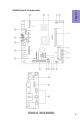
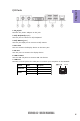
VX900-I2 USER MANUAL Chapter 1 Motherboard Components 3
Chapter 1 4 Table of Motherboard Components LABEL 1. CPU 2. CPU_FAN 3. SPK_MONO 4. DIMM_1 5. SATA_HDD 6. F_USB1~2 7. F_PANEL 8. F_AUDIO 9. SATA1~2 10. CLR_CMOS 11. SATA_PWR 12. LDC 13. PCIEX8 14. MPE1 15. LPT_SMD 16. BZ 17. COM1~3 18. VGA2_HEADER 19. DC_IN_HEADER 20. NB COMPONENTS Onboard VIA® Eden X2 U4200/VIA® Nano Single Core U3300 4-pin CPU cooling fan connector Mono Speaker header 204-pin DDR3 Module slot Half-Slim SATA connector Front panel USB 2.
Chapter 1 I/O Ports 1. DC_IN jack Connect the power adapter to this jack. 2. PS/2 Keyboard(purple) Use this port to connect a PS/2 keyboard. 3. PS/2 Mouse(green) Use this port PS/2 port to connect a PS/2 mouse. 4. DVI-I Port You can connect the display device to the DVI-I port. 5. DP Port Use this port to connect the display device. 6. USB 2.0 Ports Use the USB 2.0 ports to connect USB 2.0 devices. 7. LAN Port Connect an RJ-45 jack to the LAN port to connect your computer to the Network.
Chapter 1 6 Memo VX900-I2 USER MANUAL
Chapter 2 Installing the Motherboard Follow these safety precautions when installing the motherboard: • • • • Wear a grounding strap attached to a grounded device to avoid damage from static electricity. Discharge static electricity by touching the metal case of a safely grounded object before working on the motherboard. Leave components in the static-proof bags.
2-3. Checking Jumper Settings The following illustration shows the location of the motherboard jumpers. Pin 1 is labeled. Chapter 2 To avoid the system instability after clearing CMOS, we recommend users to enter the main BIOS setting page to “Load Default Settings” and then “Save and Exit Setup”.
2-4. Installing Hardware • • • • This motherboard accommodates two memory modules. It can support one 204-pin DDR3 1066. Do not remove any memory module from its antistatic packaging until you are ready to install it on the motherboard. Handle the modules only by their edges. Do not touch the components or metal parts. Always wear a grounding strap when you handle the modules. You must install one module. Total memory capacity is 8 GB. Refer to the following to install the memory modules.
2-4-2. Installing Add-on Cards The slots on this motherboard are designed to hold expansion cards and connect them to the system bus. Expansion slots are a means of adding or enhancing the motherboard’s features and capabilities. With these efficient facilities, you can increase the motherboard’s capabilities by adding hardware that performs tasks that are not part of the basic system. Chapter 2 MPE1 Slots The mini PCI Express x1 slot is for extending usage. It supports a full-card.
1 Remove a blanking plate from the system case corresponding to the slot you are going to use. 2 Install the edge connector of the add-on card into the expansion slot. Ensure that the edge connector is correctly seated in the slot. 3 Secure the metal bracket of the card to the system case with a screw. 1. For some add-on cards, for example graphics adapters and network adapters, you have to install drivers and software before you can begin using the add-on card.
2-4-3. Connecting Optional Devices Refer to the following for information on connecting the motherboard’s optional devices: Chapter 2 No. Components No. 1 SATA_HDD 5 Components LPT 2 F_USB1~2 6 COM1~3 3 F_AUDIO1 7 VGA2_HEADER 4 SATA1~2 —— —— 1.
2. F_USB1~2: Front Panel USB 2.0 headers Chapter 2 The motherboard has two USB 2.0 headers supporting four USB 2.0 ports. Additionally, some computer cases have USB ports at the front of the case. If you have this kind of case, use auxiliary USB connector to connect the front-mounted ports to the motherboard. Please make sure that the USB cable has the same pin assignment as indicated above. A different pin assignment may cause damage or system hangup. 3.
AC’ 97 Audio Configuration: To enable the front panel audio conne-ctor to support AC97 Audio mode. If you use AC’ 97 Front Panel, please tick off the option of “ Disabled Front Panel Detect ”. If you use HD Audio Front Panel, please don’ t tick off “Disabled Front Panel Detect ” . Chapter 2 * For reference only If you use AC’ 97 Front Panel, please don’ t tick off “Using Front Jack Detect ”. If you use HD Audio Front Panel, please tick off the option of “ Using Front Jack Detect ”.
4. SATA1~2: Serial ATA connectors Chapter 2 SATA1/2 connectors support the Serial ATA 3.0Gb/s device. Simpler disk drive cabling and easier PC assembly. It eliminates limitations of the current Parallel ATA interface. But maintains register compatibility and sofeware compatibility with Parallel ATA. 5. LPT_SMD: Onboard parallel port Header This is a header that can be used to connect to the printer, scanner or other devices.
6. COM1~3: Onboard serial port headers Connect a serial port extension bracket to this header to add a serial port to your system. Chapter 2 7. VGA2_HEADER: Chassis Intrusion Detect Header This header is used to connect the display device.
2-4-4. Installing a SATA Hard Drive This section describes how to install a SATA Hard Drive. Your motherboard features two SATA connectors supporting a total of two drives. SATA refers to Serial ATA (Advanced Technology Attachment) is the standard interface for the IDE hard drives which are currently used in most PCs. These connectors are well designed and will only fit in one orientation. Locate the SATA connectors on the motherboard and follow the illustration below to install the SATA hard drives.
2-4-7. Connecting Case Components After you have installed the motherboard into a case, you can begin connecting the motherboard components. Refer to the following: Chapter 2 No. Components 1 CPU_FAN 2 SPK_MONO 3 F_PANEL 4 SATA_PWR 5 DC_IN_HEADER 1. CPU_FAN (CPU cooling FAN Power Connector) Connect the CPU cooling fan cable to CPU_FAN. Users please note that the fan connector supports the CPU cooling fan of 1.1A ~ 2.2A (26.4W max) at +12V.
2. SPK_MONO: Mono Speaker Chapter 2 Connect the case speaker cable to SPK_MONO. 3. Front Panel Header The front panel header (F_PANEL) provides a standard set of switch and LED headers commonly found on ATX or Micro ATX cases.
Hard Drive Activity LED Connecting pins 2 and 4 to a front panel mounted LED provides visual indication that data is being read from or written to the hard drive. For the LED to function properly, an IDE drive should be connected to the onboard IDE interface. The LED will also show activity for devices connected to the SCSI (hard drive activity LED) connector.
Chapter 2 5. DC_IN_HEADER: DC IN power connector This concludes Chapter 2. The next chapter covers the BIOS.
Memo Chapter 2 22 VX900-I2 USER MANUAL
Chapter 3 Using BIOS About the Setup Utility The BIOS (Basic Input and Output System) Setup Utility displays the system’s configuration status and provides you with options to set system parameters. The parameters are stored in battery-backed-up CMOS RAM that saves this information when the power is turned off. When the system is turned back on, the system is configured with the values you stored in CMOS.
Press the delete key to access BIOS Setup Utility. CMOS Setup Utility - Copyright (C) 1985-2005, American Megatrends, Inc. System Information Standard CMOS Setup Advanced Setup Advanced Chipset Setup Integrated Peripherals Power Management Setup PCI/PnP Setup PC Health Status CPU Information Load Default Settings Supervisor Password User Password Save & Exit Setup Exit Without Saving : Move Enter : Select +/-/PU/PD: Value F10: Save and Exit ESC: Exit F1:General Help F9: Load Default Settings v02.
Using BIOS When you start the Setup Utility, the main menu appears. The main menu of the Setup Utility displays a list of the options that are available. A highlight indicates which option is currently selected. Use the cursor arrow keys to move the highlight to other options. When an option is highlighted, execute the option by pressing . Some options (marked with a triangle ) lead to submenus that enable you to change the values for the option.
System Information This option shows basic information about your system. CMOS Setup Utility - Copyright (C) 1985-2005, American Megatrends, Inc. System Information Processor Type Processor Speed Install Memory BIOS Version BIOS Date : : : : : VIA Nano U3300@1200MHz 1.20GHz 3328MB 08.00.16 11/06/12 Help Item Use [ENTER], [TAB] or [SHIFT-TAB] to select a field. Use [+] or [-] to configure system Date.
Standard CMOS Setup This option enables you to configure the system time and date, SATA devices, etc. CMOS Setup Utility - Copyright (C) 1985-2005, American Megatrends, Inc. Standard CMOS Setup Date Time Fri 11/16/2012 01 : 16 : 50 SATA1 SATA2 ATAPI CDROM Hard Disk Help Item Use [ENTER], [TAB] or [SHIFT-TAB] to select a field.
SATA2 Scroll to this item and press to view the following screen: CMOS Setup Utility - Copyright (C) 1985-2005, American Megatrends, Inc. SATA2 : Primary IDE Master Device Vendor Size LBA Mode Block Mode PIO Mode Async DMA Ultra DMA S.M.A.R.T. Help Item : Hard Disk : HDS728080PLA380 : 82.3GV : Supported : 16Sectors :4 : MultiWord DMA-2 : Ultra DMA-6 : Supported Chapter 3 Type LBA/Large Mode Block (Multi-Sector Transfer PIO Mode DMA Mode S.M.A.R.T.
Advanced Setup This page sets up more advanced information about your system. Handle this page with caution. Any changes can affect the operation of your computer. CMOS Setup Utility - Copyright (C) 1985-2005, American Megatrends, Inc. Advanced Setup Enabled On Enabled Removable Dev. (CD/DVD) HDS728080PLA380 Press Enter Press Enter Yes Disabled Help Item Alllows BIOS to skip certain tests while booting. This will decrease the time needed to boot the system.
Hard Disk Drives Scroll to this item and press to view the following screen: CMOS Setup Utility - Copyright (C) 1985-2005, American Megatrends, Inc. Hard Disk Drives Help Item Hard Disk Drives 1st Drive HDS728080PLA380 Specifies the boot sequence from the available devices. Chapter 3 : Move Enter : Select +/-/PU/PD: Value F10: Save and Exit ESC: Exit F1:General Help F9: Load Default Settings Press to return to the Advanced Setup page.
Advanced Chipset Setup This page sets up more advanced information about your system. Handle this page with caution. Any changes can affect the operation of your computer. CMOS Setup Utility - Copyright (C) 1985-2005, American Megatrends, Inc.
Integrated Peripherals This page sets up some parameters for peripheral devices connected to the system. CMOS Setup Utility - Copyright (C) 1985-2005, American Megatrends, Inc.
Power Management Setup This page sets up some parameters for system power management operation. CMOS Setup Utility - Copyright (C) 1985-2005, American Megatrends, Inc. Power Management Setup : Move ESC: Exit Auto Power Off Disabled Enabled Disabled Disabled Disabled Disabled Enabled Help Item Select the ACPI state used for System Suspend.
EUP Function (Enabled) This item allows user to enable or disable EUP support. Press to return to the main menu setting page. PCI / Plug and Play Setup This page sets up some parameters for devices installed on the PCI bus and those utilizing the system plug and play capability. CMOS Setup Utility - Copyright (C) 1985-2005, American Megatrends, Inc.
PC Health Status On motherboards support hardware monitoring, this item lets you monitor the parameters for critical voltages, temperatures and fan speeds. CMOS Setup Utility - Copyright (C) 1985-2005, American Megatrends, Inc.
SMART Fan start TEMP. (°C) (32) This item is used to set the start temperature of the smart fan. CPU DeltaT (+3) This item specifies the range that controls CPU temperature and keeps it from going so high or so low when smart fan works. SMART Fan Slope PWM value (4 PWM value/°C) This item is used to set the Slope Select PWM of the smart fan. CPU FAN Full Limit Temp (57°C) This item shows the limit temperature when the smart fan starts to run at full speed.
CPU Information thi page enables you to monitor or set some information of the processor you have This installed in your system. CMOS Setup Utility - Copyright (C) 1985-2005, American Megatrends, Inc. CPU Information : Move ESC: Exit Help Item Options Disabled Enabled Enabled Disabled Enter : Select +/-/PU/PD: Value F10: Save and Exit F1:General Help F9: Load Default Settings Chapter 3 Manufacturer: VIA VIA Eden U3300 @1200MHz Frequency : 1.
Load Default Settings This option opens a dialog box that lets you install stability-oriented defaults for all appropriate items in the Setup Utility. Select and then press to install the defaults. Select and then press to not install the defaults. CMOS Setup Utility - Copyright (C) 1985-2005, American Megatrends, Inc.
User Password This page helps you install or change a password. CMOS Setup Utility - Copyright (C) 1985-2005, American Megatrends, Inc. User Password User Password Help Item : Not Installed Change User Password Press Enter Install or Change the password. : Move Enter : Select +/-/PU/PD: Value F10: Save and Exit ESC: Exit F1:General Help F9: Load Default Settings User Password (Not Installed) This item indicates whether a user password has been set.
Save & Exit Setup Highlight this item and press to save the changes that you have made in the Setup Utility and exit the Setup Utility. When the Save and Exit dialog box appears, select [OK] to save and exit, or select [Cancel] to return to the main menu. CMOS Setup Utility - Copyright (C) 1985-2005, American Megatrends, Inc.
Updating the BIOS 1 If your motherboard has an item called BIOS Protect in Advanced BIOS features, disable it. (BIOS Protect prevents BIOS from being overwritte.) 2 Prepare a bootable device or create a bootable system disk. (Refer to Windows online help for information on creating a bootable system disk.) 3 Download the Flash Utility and new BIOS file from the manufacturer’s Web site. Copy these files to the bootable device. 4 Turn off your computer and insert the bootable device in your computer.
Memo Chapter 3 42 VX900-I2 USER MANUAL
Chapter 4 Trouble Shooting Start up problems during assembly After assembling the PC for the first time you may experience some start up problems. Before calling for technical support or returning for warranty, this chapter may help to address some of the common questions using some basic troubleshooting tips. You may also log onto our ECS website for more information: http:// www.ecs.com.tw/ECSWebSite/Support/Support_FAQ.
2. From the BIOS setting, try to disable the Smartfan function to let the fan run at default speed. Doing a Load Optimised Default will also disable the Smartfan. Start up problems after prolong use After a prolong period of use your PC may experience start up problems again. This may be caused by breakdown of devices connected to the motherboard such as HDD, CPU fan, etc. The following tips may help to revive the PC or identify the cause of failure. 1. Clear the CMOS values using the CLR_CMOS jumper.
45 If fail, contact RMA CLR CMOS and restart. Yes Halt at POST screen Yes Check if monitor has display Yes Check if Power Supply Unit (PSU) is working Power Bu on is pressed but PC fails to start. - need to CLRCMOS. HDD problem.
Memo Chapter 4 46 VX900-I2 USER MANUAL