
Manual

Chapter 2
9
TIGD2-I USER MANUAL
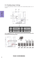
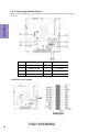
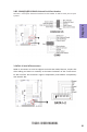
Default
5V 12V RI 5V 12V DCD
COM1 JP6 (1-3) (3-5) (7-9) (2-4) (4-6)
(
8-10
)
COM2 JP5 (1-3) (3-5) (7-9) (2-4) (4-6)
(
8-10
)
COM3 JP3 NA NA NA (1-3) (3-5) (7-9)
COM5 JP3 NA NA NA (2-4) (4-6)
(
8-10
)
PIN1
,
9
OUTPUT
PIN9 PIN1
(
8-10
)
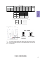
*
(7-9)
(1-3)(2-4) RS232
(3-5)(4-6) TTL
(1-3)(2-4) RS232
(3-5)(4-6) TTL
(1-3)(2-4) RS232
(3-5)(4-6) RS485
COM3 JP1
COM5 JP4
COM4 JP2
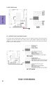
(1-3) Dual channel
(3-5) Single channel
(2-4) 18bit
(4-6) 24bit
JP7
JP7
LVDS S/D channel & output data format setting
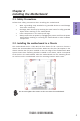
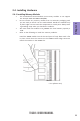
2. CLR_CMOS: Clear CMOS Jumper
To avoid the system instability after clearing CMOS, we recommend users to
enter the main BIOS setting page to “Load Default Settings” and then “Save
and Exit Setup”.
COM setting