
Manual

Chapter 2
8
TIGD2-I USER MANUAL
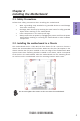
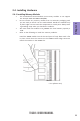
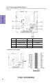
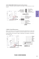
The following illustration shows the location of the motherboard jumpers. Pin 1 is
labeled.
2-3. Checking Jumper Settings
No. Components No. Components
1 JP1/2/4/3/5/6 4 JP7
2 CLR_CMOS 5 LVDS_19V
3LVDS_PWR16 LVDS_12V
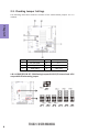
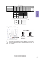
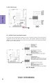
1 & 4. JP1/2/4/3/5/6 & JP7: COM Setting Jumpers & LVDS S/D channel and LVDS
output data format setting jumper