Preface Copyright This publication, including all photographs, illustrations and software, is protected under international copyright laws, with all rights reserved. Neither this manual, nor any of the material contained herein, may be reproduced without written consent of the author. Version 1.0 Disclaimer The information in this document is subject to change without notice.
Declaration of Conformity This device complies with part 15 of the FCC rules. Operation is subject to the following conditions: • This device may not cause harmful interference. • This device must accept any interference received, including interference that may cause undesired operation.
TABLE OF CONTENTS Preface i Chapter 1 1 Introducing the Motherboard 1 Introduction...........................................................................................1 Specifications......................................................................................2 Motherboard Components................................................................3 I/O Ports...............................................................................................
Chapter 4 47 Trouble Shooting 47 Start up problems during assembly..............................................47 Start up problems after prolong use............................................48 Maintenance and care tips..............................................................48 Basic Troubleshooting Flowchart.....................................................
Introduction Chapter 1 Chapter 1 Introducing the Motherboard Thank you for choosing the TIGD2-I motherboard of high performance, enhanced function. This motherboard has Onboard D2550 CPU with a Thin Mini-ITX form factor of 170 x 170 mm. This motherboard is based on Intel® NM10 Express Chipset. It supports up to 4 GB of system memory with single channel DDR3 SO-DIMM 1066/800 MHz. One optional PCI slot is supported. It implements an EHCI compliant interface that provides eight USB 2.0 ports (four USB 2.
Chapter 1 2 Specifications CPU • • Intel® Onboard D2550 CPU Intel TDP 10W Chipset • Intel ® NM10 Chipset Memory • • • Single channel DDR3 SO-DIMM memory architecture 1 x 204-pin DDR3 SO-DIMM sockets support up to 4 GB Supports DDR3 1066/800 MHz DDR3 SDRAM Expansion Slots Storage • 1 x PCI slot • Audio • Supported by Intel® NM10 Express Chipset - 2 x Serial ATA 3.0Gb/s devices Realtek ALC662 VD - 2.
• AMI BIOS with 16Mb SPI Flash ROM - Supports Plug and Play, STR(S3)/STD(S4), Multi-Language - Supports Hardware Monitor - Supports ACPI 3.
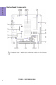
Chapter 1 Motherboard Components This picture may be different due to Optional Features on speccifications.
LABEL 1. CPU 2. SYS_FAN 3. DIMM1 4. PRINTER 5. COM3/4/2/1/6 6. ATX_POWER 7. JP1/2/4/3/5/6 8. F_PANEL 9. DIO 10. SATA1~2 11. COM5 12. PCI 13. ODD_PWR 14. HDD_PWR 15. CLR_CMOS 16. F_AUDIO 17. F_USB1~2 18. LVDS_PWR1 19. LVDS 20. JP7 21. LVDS_19V 22. LVDSPW_CONN 23. LVDS_12V COMPONENTS Onboard D2550 CPU 4-pin system cooling fan connector 204-pin DDR3 SDRAM SO-DIMM Printer header Onboard serial port headers 20-pin ATX power connector COM setting jumpers Front panel switch/LED header DIO header Serial ATA 3.
Chapter 1 I/O Ports 1. DC_IN Port Connect the DC_IN port to the power adapter. 2. PS/2 Mouse(green) Use the upper PS/2 port to connect a PS/2 mouse. 3. PS/2 Keyboard(purple) Use the lower PS/2 port to connect a PS/2 keyboard. 4. VGA Port Connect your monitor to the VGA port. 5. DVI Port You can connect the display device to the DVI port. 6. LAN Ports Connect an RJ-45 jack to the LAN port to connect your computer to the Network.
Chapter 2 Installing the Motherboard Follow these safety precautions when installing the motherboard: • • • • Wear a grounding strap attached to a grounded device to avoid damage from static electricity. Discharge static electricity by touching the metal case of a safely grounded object before working on the motherboard. Leave components in the static-proof bags.
2-3. Checking Jumper Settings The following illustration shows the location of the motherboard jumpers. Pin 1 is labeled. Chapter 2 No. Components No. 1 JP1/2/4/3/5/6 4 Components JP7 2 CLR_CMOS 5 LVDS_19V 3 LVDS_PWR1 6 LVDS_12V 1 & 4.
COM setting 5V (1-3) (1-3) NA NA PIN9 12V (3-5) (3-5) NA NA COM3 JP1 COM5 JP4 COM4 JP2 RI (7-9) (7-9) NA NA 5V (2-4) (2-4) (1-3) (2-4) (1-3)(2-4) (3-5)(4-6) (1-3)(2-4) (3-5)(4-6) (1-3)(2-4) (3-5)(4-6) PIN1 12V (4-6) (4-6) (3-5) (4-6) Default DCD (8-10) (8-10) * (8-10) (7-9) (7-9) (8-10) RS232 TTL RS232 TTL RS232 RS485 Chapter 2 PIN1,9 OUTPUT COM1 JP6 COM2 JP5 COM3 JP3 COM5 JP3 LVDS S/D channel & output data format setting JP7 JP7 (1-3) (3-5) (2-4) (4-6) Dual channel Single channel 18bit 24
3. LVDS_PWR1: LVDS Power Select Jumper Chapter 2 5&6.
2-4. Installing Hardware • • • • This motherboard accommodates one memory module. It can support one 204-pin DDR3 SO-DIMM 1066/800. Do not remove any memory module from its antistatic packaging until you are ready to install it on the motherboard. Handle the modules only by their edges. Do not touch the components or metal parts. Always wear a grounding strap when you handle the modules. You must install one module in SO_DIMM1 slot. Total memory capacity is 4 GB.
2-4-2. Installing Add-on Cards The slots on this motherboard are designed to hold expansion cards and connect them to the system bus. Expansion slots are a means of adding or enhancing the motherboard’s features and capabilities. With these efficient facilities, you can increase the motherboard’s capabilities by adding hardware that performs tasks that are not part of the basic system. Chapter 2 PCI Slot This motherboard is equipped with one standard PCI slot.
1 Remove a blanking plate from the system case corresponding to the slot you are going to use. 2 Install the edge connector of the add-on card into the expansion slot. Ensure that the edge connector is correctly seated in the slot. 3 Secure the metal bracket of the card to the system case with a screw. 1. For some add-on cards, for example graphics adapters and network adapters, you have to install drivers and software before you can begin using the add-on card.
2-4-3. Connecting Optional Devices Refer to the following for information on connecting the motherboard’s optional devices: Chapter 2 No. Components No.
2 & 5. COM2/1/4/3/6 & COM5: Onboard Serial Port Headers Chapter 2 Connect a serial port extension bracket to this header to add a serial port to your system. 3. SATA1~2: Serial ATA connectors SATA1~2 connectors are used to support the Serial ATA 3.0Gb/s devices, simpler disk drive cabling and easier PC assembly. It eliminates limitations of the current Parallel ATA interface. But maintains register compatibility and software compatibility with Parallel ATA.
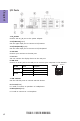
4. DIO: DIO Header Chapter 2 6. F_AUDIO: Front Panel Audio Header The front panel audio header allows the user to install auxiliary front-oriented microphone and line-out ports for easier access. This header supports HD audio by default. If you want connect an AC’ 97 front panel audio to HD onboard headers, please set as below picture.
AC’ 97 Audio Configuration: To enable the front panel audio connector to support AC97 Audio mode. Chapter 2 If you use AC’ 97 Front Panel, please tick off the option of “ Disabled Front Panel Detect ”. If you use HD Audio Front Panel, please don’ t tick off “Disabled Front Panel Detect ” . * For reference only If you use AC’ 97 Front Panel, please don’ t tick off “Using Front Jack Detect ”. If you use HD Audio Front Panel, please tick off the option of “Using Front Jack Detect ”.
7. F_USB1~2: Front Panel USB 2.0 headers The motherboard has two USB 2.0 headers supporting four USB 2.0 ports. Additionally, some computer cases have USB ports at the front of the case. If you have this kind of case, use auxiliary USB connector to connect the front-mounted ports to the motherboard. Chapter 2 Please make sure that the USB cable has the same pin assignment as indicated above. A different pin assignment may cause damage or system hangup. 8.
2-4-4. Installing a Hard Disk Drive/Optical Disk Drive/SATA Hard Drive This section describes how to install a Hard Disk Drive/Optical Disk Drive/SATA Hard Drive. Your motherboard features two SATA connectors supporting a total of two drives. SATA refers to Serial ATA (Advanced Technology Attachment) is the standard interface for the IDE hard drives which are currently used in most PCs. These connectors are well designed and will only fit in one orientation.
2-4-5. Connecting Case Components After you have installed the motherboard into a case, you can begin connecting the motherboard components. Refer to the following: Chapter 2 No. Components No. 1 LVDSPW_CONN 4 Components F_PANEL 2 SYS_FAN 5 HDD_PWR 3 ATX_POWER 6 ODD_PWR 1.
2. SYS_FAN : System Cooling FAN Power Connector Chapter 2 Connect the system cooling fan cable to SYS_FAN. 3. ATX_POWER: ATX 20-pin Power Connector Connect the standard power supply connector to ATX_POWER.
4. Front Panel Header The front panel header (F_PANEL) provides a standard set of switch and LED headers commonly found on ATX or Micro ATX cases. Chapter 2 Hard Drive Activity LED Connecting pins 1 and 3 to a front panel mounted LED provides visual indication that data is being read from or written to the hard drive. For the LED to function properly, an IDE drive should be connected to the onboard IDE interface.
5 & 6. HDD_PWR & ODD_PWR: HDD Power & ODD Power Connectors Chapter 2 Connect the HDD power cable to HDD_PWR. Connect the ODD power cable to ODD_PWR. This concludes Chapter 2. The next chapter covers the BIOS.
Memo Chapter 2 24 TIGD2-I USER MANUAL
Chapter 3 Using BIOS About the Setup Utility The BIOS (Basic Input and Output System) Setup Utility displays the system’s configuration status and provides you with options to set system parameters. The parameters are stored in battery-backed-up CMOS RAM that saves this information when the power is turned off. When the system is turned back on, the system is configured with the values you stored in CMOS.
Press the delete or F2 key to access BIOS Setup Utility. Aptio Setup Utility - Copyright (C) 2011 American Megatrends, Inc. Main Advanced Chipset Tweak Boot Security Exit Set the Date. Use Tab to switch between Data elements.
In this manual, default values are enclosed in parenthesis. Submenu items are denoted by a triangle . The default BIOS setting for this motherboard apply for most conditions with optimum performance. We do not suggest users change the default values in the BIOS setup and take no responsibility to any damage caused by changing the BIOS settings. BIOS Navigation Keys The BIOS navigation keys are listed below: KEY FUNCTION Exits the current menu Scrolls through the items on a menu +/- Change Opt.
Main Menu When you enter the BIOS Setup program, the main menu appears, giving you an overview of the basic system information. Select an item and press to display the submenu. Aptio Setup Utility - Copyright (C) 2011 American Megatrends, Inc. Main Advanced Chipset Tweak Boot Security Exit Set the Date. Use Tab to switch between Data elements.
Advanced Menu The Advanced menu items allow you to change the settings for the CPU and other system. Aptio Setup Utility - Copyright (C) 2011 American Megatrends, Inc. Advanced Chipset Tweak Boot Security Exit Launch PXE OpROM Legacy OpROM Support Launch PXE OpROM Launch Storage OpROM [Disabled] [Enabled] :Select Screen :Select Item Enter : Select +/- : Change Opt.
PC Health Status On motherboards support hardware monitoring, this item lets you monitor the parameters for critical voltages, temperatures and fan speeds. Aptio Setup Utility - Copyright (C) 2011 American Megatrends, Inc. Main Advanced Chipset Tweak Boot Security Exit CPU Over Temperature Warning PC Health Status CPU Temperature System Temperature CPU Vcore CPU Over Temperature Warning : +46°C : +37°C : +1.184 V [75] Chapter 3 :Select Screen :Select Item Enter : Select +/- : Change Opt.
Power Management Setup This page sets up some parameters for system power management operation. Aptio Setup Utility - Copyright (C) 2011 American Megatrends, Inc. Main Advanced Chipset Tweak Boot Security Exit Power Management Setup About Resume by Ring [Disabled] [Disabled] [Disabled] [Disabled [Disabled] [Disabled] :Select Screen :Select Item Enter : Select +/- : Change Opt. F1:General Help F2:Previous Values F3:Optimized Defaults F4:Save & Exit ESC:Exit Version 2.14.1219.
ACPI Setting The item in the menu shows the highest ACPI sleep state when the system enters suspend. Aptio Setup Utility - Copyright (C) 2011 American Megatrends, Inc. Main Advanced Chipset Tweak Boot Security Exit ACPI Settings ACPI Sleep State [S3 (Suspend to RAM)] Select the highest ACPI sleep state the system will enter when the SUSPEND button is pressed. Chapter 3 :Select Screen :Select Item Enter : Select +/- : Change Opt.
D Intel(R) Atom(TM) CPU D2550 @ 1.86GHz This is display-only field and displays the information of the CPU installed in your computer. EM64T (Supported) This item shows the computer supports EMT64. Processor Speed (1865MHz) This item shows the current processor speed. Processor Stepping (30661) This item shows the processor stepping version. Hyper-Threading Technology (Supported) This item shows that your computer supports Intel HT technology or not.
SATA Configuration Use this item to show the mode of serial SATA configuration options. Aptio Setup Utility - Copyright (C) 2011 American Megatrends, Inc. Main Advanced Chipset Tweak Boot Security Exit SATA Mode Serial-ATA Controller SATA Port1 SATA Port2 [IDE Mode] [Enhanced] HL-DT-STDVD-RO ATAPI ST3160318AS 157GB Select a configuration for SATA Controller. Chapter 3 :Select Screen :Select Item Enter : Select +/- : Change Opt.
USB Configuration Scroll to this item and press to view the following screen: Aptio Setup Utility - Copyright (C) 2011 American Megatrends, Inc. Main Advanced Chipset Tweak Boot Security Exit USB Configuration [Enabled] [Enabled] :Select Screen :Select Item Enter : Select +/- : Change Opt. F1:General Help F2:Previous Values F3:Optimized Defaults F4:Save & Exit ESC:Exit Version 2.14.1219. Copyright (C) 2011, American Megatrends, Inc.
Super IO Configuration Use this item to show the information of the Super IO Configuration. Please do not change IRQ or I/O port at random. Aptio Setup Utility - Copyright (C) 2011 American Megatrends, Inc.
Serial Port 2 Configuration Scroll to this item and press to view the following screen: Aptio Setup Utility - Copyright (C) 2011 American Megatrends, Inc. Main Advanced Chipset Tweak Boot Security Exit Serial Port Device Settings [Enabled] IO=2F8h; IRQ=3; Change Settings [Auto] Enable or Disable Serial Port (COM) :Select Screen :Select Item Enter : Select +/- : Change Opt. F1:General Help F2:Previous Values F3:Optimized Defaults F4:Save & Exit ESC:Exit Version 2.14.1219.
Serial Port (Enabled) This item allows you to enable or disable serial port. Device Settings (IO=3E8h; IRQ=7) This item shows the information of the device settings. Change Settings (Auto) Use this item to change device settings. Press to return to the Super IO Configuration page. Serial Port 4 Configuration Scroll to this item and press to view the following screen: Chapter 3 Aptio Setup Utility - Copyright (C) 2011 American Megatrends, Inc.
Serial Port 5 Configuration Scroll to this item and press to view the following screen: Aptio Setup Utility - Copyright (C) 2011 American Megatrends, Inc. Main Advanced Chipset Tweak Boot Security Exit Serial Port Device Settings [Enabled] IO=2F0h; IRQ=7; Change Settings [Auto] Enable or Disable Serial Port (COM) :Select Screen :Select Item Enter : Select +/- : Change Opt. F1:General Help F2:Previous Values F3:Optimized Defaults F4:Save & Exit ESC:Exit Version 2.14.1219.
Chipset Menu The chipset menu items allow you to change the settings for the North Bridge chipset, South Bridge chipset and other system. Aptio Setup Utility - Copyright (C) 2011 American Megatrends, Inc. Main Advanced Chipset Tweak Boot Security Exit North Bridge Parameters North Bridge South Bridge Chapter 3 :Select Screen :Select Item Enter : Select +/- : Change Opt. F1:General Help F2:Previous Values F3:Optimized Defaults F4:Save & Exit ESC:Exit Version 2.14.1219.
LCD Panel Type (1024x768 LVDS) This item enables you to select which resolution to be used for LVDS panel. Press to return to the chipset menu page. South Bridge Scroll to this item and press to view the following screen: Aptio Setup Utility - Copyright (C) 2011 American Megatrends, Inc. Main Advanced Chipset Tweak Boot Security Exit [Enabled] [Power Off] HD Audio Controller :Select Screen :Select Item Enter : Select +/- : Change Opt.
Tweak Menu This page enables you to set the clock speed and system bus for your system. The clock speed and system bus are determined by the kind of processor you have installed in your system. Aptio Setup Utility - Copyright (C) 2011 American Megatrends, Inc.
Boot Menu This page enables you to set the keyboard NumLock state. Aptio Setup Utility - Copyright (C) 2011 American Megatrends, Inc. Main Advanced Chipset Tweak Boot Security Exit Bootup NumLock State Quiet Boot [On] [Disabled] Set Boot Priority 1st Boot 2nd Boot 3rd Boot 4th Boot 5th Boot 6th Boot 7th Boot 8th Boot [Hard Disk: ST31603...] [CD/DVD: HL-DT-STDV...
Security Menu This page enables you to set setup administrator and password. Aptio Setup Utility - Copyright (C) 2011 American Megatrends, Inc. Main Advanced Chipset Tweak Boot Security Exit Administrator Password Chapter 3 44 Set Administrator Password :Select Screen :Select Item Enter : Select +/- : Change Opt. F1:General Help F2:Previous Values F3:Optimized Defaults F4:Save & Exit ESC:Exit Version 2.14.1219. Copyright (C) 2011, American Megatrends, Inc.
Exit Menu This page enables you to exit system setup after saving or without saving the changes. Aptio Setup Utility - Copyright (C) 2011 American Megatrends, Inc. Main Advanced Chipset Tweak Boot Security Exit Save Options Save Changes Discard Changes Restore Defaults Save as User Defaults Restore User Defaults Boot Override SATA PM: HL-DT-STDVD-ROM DH10 SATA SM: ST3160318AS :Select Screen :Select Item Enter : Select +/- : Change Opt.
Updating the BIOS You can download and install updated BIOS for this motherboard from the manufacturer’s Web site. New BIOS provides support for new peripherals, improvements in performance, or fixes for known bugs. Install new BIOS as follows: Chapter 3 1 If your motherboard has a BIOS protection jumper, change the setting to allow BIOS flashing. 2 If your motherboard has an item called Firmware Write Protect in Advanced BIOS features, disable it.
Chapter 4 Trouble Shooting Start up problems during assembly After assembling the PC for the first time you may experience some start up problems. Before calling for technical support or returning for warranty, this chapter may help to address some of the common questions using some basic troubleshooting tips. You may also log onto our website for more information. a) System does not power up and the fans are not running. 2.
2. From the BIOS setting, try to disable the Smartfan function to let the fan run at default speed. Doing a Load Optimised Default will also disable the Smartfan. Start up problems after prolong use After a prolong period of use your PC may experience start up problems again. This may be caused by breakdown of devices connected to the motherboard such as HDD, CPU fan, etc. The following tips may help to revive the PC or identify the cause of failure. 1. Clear the CMOS values using the CLR_CMOS jumper.
49 If fail, contact RMA CLR CMOS and restart. Yes Halt at POST screen Yes Check if monitor has display Yes Check if Power Supply Unit (PSU) is working Power Bu on is pressed but PC fails to start. - need to CLRCMOS. HDD problem.
Memo Chapter 4 50 TIGD2-I USER MANUAL