
Owner manual


19
Installing the Motherboard
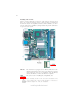
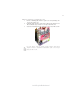
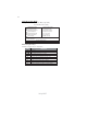
USB3: Front Panel USB header
The motherboard has four USB ports installed on the rear edge I/O port array.
Additionally, some computer cases have USB ports at the front of the case. If you
have this kind of case, use auxiliary USB connector to connect the front-mounted
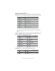
Please make sure that the USB cable has the same pin assignment as
indicated above. A different pin assignment may cause damage or sys-
tem hang-up.
1 VCC Power
2 VCC Power
3 USBP2-N Negative data signal of
4 USBP3-N Positive data signal of
5 USBP2-P Positive data signal of
6 USBP3-P Negative data signal of
7 GND System
8 GND System
9 Key No pin
10 OC# Over current detection of
Pin Signal Name Function
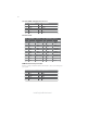
LVDS1~LVDS2(Max Peak current 2.5A): Low Voltage Differential Sig-
naling Transmitter Interface Channel A~B
LVDS3(Max Peak current 1.7A): LVDS power header
1 VCC12M1
2 VCC5
3 VCC12M1
4 LVDS-BKLTEN
Pin Signal Name Pin Signal Name
5 GND
- -
1 VCC
3 VCC
5 Data: YAM0
7 Data: YAP0
9 GND
Pin Signal Name Pin Signal Name
11 Data: YAM1
13 Data: YAP1
15 GND
17 Data: YAM2
19 Data: YAP2
2 VCC
4 VCC
6 Data: YAM3
8 Data: YAP3
10 GND
12 Clocl:CLKAM
14 Clock: CLKAP
16 GND
18 GND
20 GND