i Preface Copyright This publication, including all photographs, illustrations and software, is protected under international copyright laws, with all rights reserved. Neither this manual, nor any of the material contained herein, may be reproduced without written consent of the author. Version 2.0B Disclaimer The information in this document is subject to change without notice.
ii Declaration of Conformity This device complies with part 15 of the FCC rules. Operation is subject to the following conditions: • • This device may not cause harmful interference, and This device must accept any interference received, including interference that may cause undesired operation. Canadian Department of Communications This class B digital apparatus meets all requirements of the Canadian Interferencecausing Equipment Regulations.
iii TABLE OF CONTENTS Preface i Chapter 1 1 Introducing the Motherboard 1 Introduction................................................................................................1 Features.......................................................................................................2 Motherboard Components.......................................................................4 Chapter 2 7 Installing the Motherboard 7 Safety Precautions.....................................................
iv Advanced Chipset Features.........................................................30 Integrated Peripherals.................................................................32 Power Management Setup...........................................................36 PNP/PCI Configurations.............................................................38 PC Health Status.........................................................................39 Frequency/Voltage Control..............................................
1 Chapter 1 Introducing the Motherboard Introduction Thank you for choosing PMI8M motherboard of great performance and with enhanced function. This motherboard carries an ITX form factor of 170 x 170 mm. PMI8M supports Socket 479 Pentium M and Celeron processors with system bus speeds up to 400MHz. The motherboard may support 855GME/852GM Northbridges and ICH4M Southbridge.
2 Features Processor This motherboard uses a 479-pin socket that carries the following features: • • Accommodates Intel Pentium M/Celeron processors Supports a system bus (FSB) of 400 MHz Chipset Intel’s 855GME/852GM Northbridge (NB) and ICH4M Southbridge (SB) chipsets are based on an innovative and scalable architecture with proven reliability and performance.
3 Expansion Options The motherboard comes with the following expansion options: • • • • One 32-bit PCI slot Two IDE connectors which support four IDE devices One floppy disk drive interface One CF socket (optional) The motherboard supports Ultra DMA bus mastering with transfer rates of 100/66/ 33MB/s.
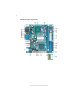
4 Motherboard Components Introducing the Motherboard
5 Table of Motherboard Components LABEL COMPONENTS 1. CPU Socket 479 socket for Pentium M/Celeron CPUs 2. CPU_FAN CPU cooling fan connector 3. DIMM1 184-pin DDR SDRAM slot 4. SYS_FAN System cooling fan connector 5. CF_PWR* CF power voltage jumper 6. ATX_POWER Standard 20-pin ATX power connector 7. LPT LPT header 8. FDD Floppy disk drive connector 9. IDE2 Secondary IDE connector 10. IDE1 Primary IDE connector 11. PANEL Front Panel switch/LED header 12.
6 Memo Introducing the Motherboard
7 Chapter 2 Installing the Motherboard Safety Precautions • • • • • Follow these safety precautions when installing the motherboard Wear a grounding strap attached to a grounded device to avoid damage from static electricity Discharge static electricity by touching the metal case of a safely grounded object before working on the motherboard Leave components in the static-proof bags they came in Hold all circuit boards by the edges.
8 Do not over-tighten the screws as this can stress the motherboard. Checking Jumper Settings This section explains how to set jumpers for correct configuration of the motherboard. Setting Jumpers Use the motherboard jumpers to set system configuration options. Jumpers with more than one pin are numbered. When setting the jumpers, ensure that the jumper caps are placed on the correct pins. The illustrations show a 2-pin jumper. When the jumper cap is placed on both pins, the jumper is SHORT.
9 Checking Jumper Settings The following illustration shows the location of the motherboard jumpers. Pin 1 is labeled. Jumper Settings Jumper Type Description Setting (default) CLR_CMOS CLR_CMOS 3-pin CLEAR CMOS 1-2: NORMAL 2-3: CLEAR CMOS Before clearing the CMOS, make sure to turn the system off.
10 Connecting Case Components After you have installed the motherboard into a case, you can begin connecting the motherboard components. Refer to the following: 1 2 3 4 Connect the CPU cooling fan cable to CPU_FAN. Connect the system cooling fan connector to SYS_FAN. Connect the case switches and indicator LEDs to the PANEL. Connect the standard power supply connector to ATX_POWER.
11 ATX_POWER: ATX 20-pin Power Connector Pin Signal Name Pin Signal Name 1 VCC3 11 VCC3 2 3 4 5 6 7 8 9 10 VCC3 12 13 14 15 16 17 18 19 20 -12V GND VCC GND VCC GND PWROK 5VSB +12V GND PS-ON# GND GND GND -5V VCC VCC Front Panel Header The front panel header (PANEL) provides a standard set of switch and LED headers commonly found on ATX or micro-ATX cases.
12 Power/Sleep/Message waiting LED Connecting pins 2 and 4 to a single or dual-color, front panel mounted LED provides power on/off, sleep, and message waiting indication. Reset Switch Supporting the reset function requires connecting pin 5 and 7 to a momentarycontact switch that is normally open. When the switch is closed, the board resets and runs POST. Power Switch Supporting the power on/off function requires connecting pins 6 and 8 to a momentary-contact switch that is normally open.
13 CPU Installation Procedure The following illustration shows CPU installation components. 1 2 3 4 5 6 Cut edge Install your CPU. Use a screwdriver to make the CPU socket in tension release position. Locate the CPU cut edge (the corner with the pin hold noticeably missing). Align and insert the CPU correctly. Use a screwdriver to screw up the CPU socket. Apply thermal grease on top of the CPU Fasten the cooling fan supporting base onto the CPU socket on the motherboard.
14 Installation Procedure Refer to the following to install the memory modules. 1 2 3 4 5 6 This motherboard supports unbuffered DDR SDRAM only. Push the latches on each side of the DIMM slot down. Align the memory module with the slot. The DIMM slots are keyed with notches and the DIMMs are keyed with cutouts so that they can only be installed correctly. Check that the cutouts on the DIMM module edge connector match the notches in the DIMM slot.
15 IDE2: Secondary IDE Connector The second drive on this controller must be set to slave mode. The configuration is the same as IDE1. IDE devices enclose jumpers or switches used to set the IDE device as MASTER or SLAVE. Refer to the IDE device user’s manual. Installing two IDE devices on one cable, ensure that one device is set to MASTER and the other device is set to SLAVE. The documentation of your IDE device explains how to do this. About UltraDMA This motherboard supports UltraDMA 100/66/33.
16 Installing Add-on Cards The slots on this motherboard are designed to hold expansion cards and connect them to the system bus. Expansion slots are a means of adding or enhancing the motherboard’s features and capabilities. With these efficient facilities, you can increase the motherboard’s capabilities by adding hardware that performs tasks that are not part of the basic system. PCI Slot This motherboard is equipped with one PCI slot.
17 Follow these instructions to install an add-on card: 1 2 3 Remove a blanking plate from the system case corresponding to the slot you are going to use. Install the edge connector of the add-on card into the expansion slot. Ensure that the edge connector is correctly seated in the slot. Secure the metal bracket of the card to the system case with a screw.
18 Connecting Optional Devices Refer to the following for information on connecting the motherboard’s optional devices: DIO: DIO port header Pin 1 3 5 7 Signal Name Pin 2 4 6 8 GPIO 32 GPIO 33 GPIO 34 GND Signal Name GPIO 36 GPIO 37 GPIO 38 GND AUDIO: Front Panel Audio header This header allows the user to install auxiliary front-oriented microphone and lineout ports for easier access.
19 USB3: Front Panel USB header The motherboard has four USB ports installed on the rear edge I/O port array. Additionally, some computer cases have USB ports at the front of the case.
20 JP1~JP2: COM1~4 Ring function selectors Pin Signal Name Pin 1 3 5 VCC12 2 4 6 7 XNRI1 8 9 NRI1 VCC5 XNRI1 Signal Name VCC5 XNRI2 VCC12 XNRI2 10 NRI2 LPT: LPT header Pin Signal Name Pin Signal Pin Name Signal Name Function Function 1 3 5 7 9 11 13 15 17 STB# Strobe D1 Data 1 SLIN# Select In 2 4 6 8 10 12 14 16 18 GND Chassis Ground 19 GND Chassis Ground 20 GND Chassis Ground Chassis Ground D3 Data 3 D5 Data 5 D7 Data 7 BUSY Busy SLCT Select ERR# Error D0 Da
21 Connecting I/O Devices The backplane of the motherboard has the following I/O ports: PS2 Mouse Use the upper PS/2 port to connect a PS/2 pointing device. PS2 Keyboard Use the lower PS/2 port to connect a PS/2 keyboard. Serial Port (COM1~COM3) Use the COM ports to connect serial devices such as mice or fax/modems. VGA Port Connect your monitor to the VGA port. LAN Ports (LAN2 optional) Connect an RJ-45 jack to the LAN port to connect your computer to the Network.
22 Memo Installing the Motherboard
23 Chapter 3 Using BIOS About the Setup Utility The computer uses the latest Award BIOS with support for Windows Plug and Play. The CMOS chip on the motherboard contains the ROM setup instructions for configuring the motherboard BIOS. The BIOS (Basic Input and Output System) Setup Utility displays the system’s configuration status and provides you with options to set system parameters. The parameters are stored in battery-backed-up CMOS RAM that saves this information when the power is turned off.
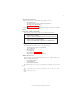
24 Press DEL to enter SETUP Pressing the delete key accesses the BIOS Setup Utility: Phoenix-AwardBIOS CMOS Setup Utility: f Standard CMOS Features f Advanced BIOS Features f Advanced Chipset Features fIntegrated Peripherals f Power Management Setup f PnP/PCI Configurations f PC Health Status f Frequency/Voltage Control Load Fail-Safe Defaults Load Optimized Defaults Set Supervisor Password Set User Password Save & Exit Setup Exit Without Saving Esc: Quit F9: Menu in BIOS F10: Save & Exit Setup mnlk :
25 Updating the BIOS You can download and install updated BIOS for this motherboard from the manufacturer’s Web site. New BIOS provides support for new peripherals, improvements in performance, or fixes for known bugs. Install new BIOS as follows: 1 2 3 4 5 6 7 8 If your motherboard has a BIOS protection jumper, change the setting to allow BIOS flashing. If your motherboard has an item called Firmware Write Protect in Advanced BIOS features, disable it.
26 Standard CMOS Features This option displays basic information about your system. Phoenix-AwardBIOS CMOS Setup Utility Standard CMOS Features Date (mm:dd:yy) Time (hh:mm:ss) IDE Primary Master IDE Primary Slave IDE Secondary Master IDE Secondary Slave Tue, July 11 2001 12 : 8 : 59 [None] [None] [None] [None] Drive A Floppy 3 Mode Support [1.44M, 3.5 in.
27 If you are setting up a new hard disk drive that supports LBA mode, more than one line will appear in the parameter box. Choose the line that lists LBA for an LBA drive. IDE Primary/Secondary Master/Slave (Auto) Leave this item at Auto to enable the system to automatically detect and configure IDE devices on the channel. If it fails to find a device, change the value to Manual and then manually configure the drive by entering the characteristics of the drive in the items described below.
28 Advanced BIOS Features This option defines advanced information about your system. f CPU Feature [Press Enter] [Enabled] [Enabled] [Enabled] [Floppy] [HDD-0] [CDROM] [Enabled] [Disabled] [On] [Fast] [Enalbed] [Disabled] 6 250 [Setup] [Enabled] [1.
29 CPU L1 & L2 Cache (Enabled) All processors that can be installed in this motherboard use internal level 1 (L1) and external level 2 (L2) cache memory to improve performance. Leave this item at the default value for better performance. CPU Hyper-Threading (Enabled) This item is only available when the chipset supports Hyper-Threading and you are using a Hyper-Threading CPU. Quick Power On Self Test (Enabled) Enable this item to shorten the power on self testing (POST) and have your system start up faster.
30 APIC Mode (Enabled) This option enables or disables APIC (Advanced Programmable Interrupt Controller) functionality. The APIC is an Intel chip that provides symmetric multi-processing (SMP) for its Pentium systems. MPS Version Control For OS (1.4) The BIOS supports versions 1.1 and 1.4 of the Intel multiprocessor specification. Select the version supported by the operation system running on the computer.
31 • • • • CAS Latency Time (2.5): This item controls the timing delay (in clock cycles) before the DRAM starts a read command after receiving it. Active to Precharge Delay (7): This precharge time is the number of cycles it takes for DRAM to accumulate its charge before refresh. DRAM RAS# to CAS# Delay (3): This field lets you insert a timing delay between the CAS and RAS strobe signals, used when DRAM is written to, read from, or refreshed.
32 Integrated Peripherals These options display items that define the operation of peripheral components on the system’s input/output ports.
33 IDE Primary/Secondary Master/Slave UDMA (Auto) Each IDE channel supports a master device and a slave device. This motherboard supports UltraDMA technology, which provides faster access to IDE devices. If you install a device that supports UltraDMA, change the appropriate item on this list to Auto. You may have to install the UltraDMA driver supplied with this motherboard in order to use an UltraDMA device.
34 POWER ON Function (BUTTON ONLY) This feature allows you to set the method by which your system can be turned on. Hot Key Power On (Ctrl-F1) When the POWER ON Function is set to Hot Key, use this item to set the hot key combination that turns on the system. Onboard FDC Controller (Enabled) This option enables the onboard floppy disk drive controller. Onboard Serial Port1~3 (3F8/IRQ4, 2F8/IRQ3) These options are used to assign the I/O address and interrupt request (IRQ) for onboard serial port1~2.
35 POWER ON Function (BUTTON ONLY) This feature allows you to set the method by which your system can be turned on. Hot Key Power On (Ctrl-F1) When the POWER ON Function is set to Hot Key, use this item to set the hot key combination that turns on the system. Onboard FDC Controller (Enabled) This option enables the onboard floppy disk drive controller. Onboard Serial Port1~3 (3F8/IRQ4, 2F8/IRQ3) These options are used to assign the I/O address and interrupt request (IRQ) for onboard serial port1~2.
36 Power Management Setup This option lets you control system power management. The system has various power-saving modes including powering down the hard disk, turning off the video, suspending to RAM, and software power down that allows the system to be automatically resumed by certain events. The power-saving modes can be controlled by timeouts. If the system is inactive for a time, the timeouts begin counting.
37 Suspend Type (Stop Grant) If this item is set to the default Stop Grant, the CPU will go into Idle Mode during power saving mode. MODEM Use IRQ (3) If you want an incoming call on a modem to automatically resume the system from a power-saving mode, use this item to specify the interrupt request line (IRQ) that is used by the modem. You might have to connect the fax/modem to the motherboard Wake On Modem connector for this feature to work.
38 ** Reload Global Timer Events ** Global Timer (power management) events are I/O events whose occurrence can prevent the system from entering a power saving mode or can awaken the system from such a mode. In effect, the system remains alert for anything that occurs to a device that is configured as Enabled, even when the system is in a power-down mode.
39 • IRQ Resources: In the IRQ Resources submenu, if you assign an IRQ to Legacy ISA, then that Interrupt Request Line is reserved for a legacy ISA expansion card. Press to close the IRQ Resources submenu. In the Memory Resources submenu, use the first item Reserved Memory Base to set the start address of the memory you want to reserve for the ISA expansion card. Use the section item Reserved Memory Length to set the amount of reserved memory. Press to close the Memory Resources submenu.
40 • • • • • +5V 5VSB VDIMM NB Vcore VBAT (V) Frequency/Voltage Control This item enables you to set the clock speed and system bus for your system. The clock speed and system bus are determined by the kind of processor you have installed in your system.
41 Load Fail-Safe Defaults Option This option opens a dialog box that lets you install fail-safe defaults for all appropriate items in the Setup Utility: Press and then to install the defaults. Press and then to not install the defaults. The fail-safe defaults place no great demands on the system and are generally stable. If your system is not functioning correctly, try installing the fail-safe defaults as a first step in getting your system working properly again.
42 Save & Exit Setup Option Highlight this item and press to save the changes that you have made in the Setup Utility and exit the Setup Utility. When the Save and Exit dialog box appears, press to save and exit, or press to return to the main menu: Exit Without Saving Highlight this item and press to discard any changes that you have made in the Setup Utility and exit the Setup Utility.
43 Chapter 4 Using the Motherboard Software About the Software CD-ROM The support software CD-ROM that is included in the motherboard package contains all the drivers and utility programs needed to properly run the bundled products. Below you can find a brief description of each software program, and the location for your motherboard version. More information on some programs is available in a README file, located in the same directory as the software.
44 Setup Tab Setup Click the Setup button to run the software installation program. Select from the menu which software you want to install. Browse CD The Browse CD button is the standard Windows command that allows you to open Windows Explorer and show the contents of the support CD. Before installing the software from Windows Explorer, look for a file named README.TXT, INSTALL.TXT or something similar. This file may contain important information to help you install the software correctly.
45 2. Click Next. The following screen appears: 3. Check the box next to the items you want to install. The default options are recommended. 4. Click Next run the Installation Wizard. An item installation screen appears: 5. Follow the instructions on the screen to install the items. Drivers and software are automatically installed in sequence. Follow the onscreen instructions, confirm commands and allow the computer to restart a few times to complete the installation.
46 Manual Installation Insert the CD in the CD-ROM drive and locate the PATH.DOC file in the root directory. This file contains the information needed to locate the drivers for your motherboard. Look for the chipset and motherboard model; then browse to the directory and path to begin installing the drivers. Most drivers have a setup program (SETUP.EXE) that automatically detects your operating system before installation. Other drivers have the setup program located in the operating system subfolder.