i
Preface ©Copyright 2005 All Rights Reserved. The information in this document is subject to change without prior notice in order to improve reliability, design and function and does not represent a commitment on the part of the manufacturer. In no event will the manufacturer be liable for direct, indirect, special, incidental, or consequential damages arising out of the use or inability to use the product or documentation, even if advised of the possibility of such damages.
Notices FEDERAL COMMUNICATIONS COMMISSION RADIO FREQUENCY INTERFERENCE STATEMENT This equipment has been tested and found to comply with the limits for a Class B digital device, pursuant to Part 15 of the FCC Rules. These limits are designed to provide reasonable protection against harmful interference in a residential installation.
EC DECLARATION OF CONFORMITY (EUROPE) Hereby, we declares that this product is in compliance with the essential requirements and other relevant provisions of Directive 1999/5/EC as listed below Article 3.1(a): EN 60950, EN50392 Article 3.1(b): EN 301 489-1, EN 301 489-17 Article 3.2: EN 300 328, EN 301 893 0976 Caution: This equipment is intended to be used in all EU and EFTA countries. Outdoor use may be restricted to certain frequencies and/or may require a license for operation.
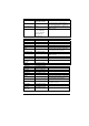
within the band 2454-2483.5 MHz Italy Luxembourg None Romania On a secondary basis. Individual license required.
Spain Not implemented 5470-5725 MHz Austria Belgium Bulgaria Cyprus France Not implemented Not implemented Not implemented Not implemented Not implemented Germany Greece Ireland Italy Not implemented Not implemented Not implemented Liechtenstein Luxembourg Not implemented None Macedonia (Rep of) Portugal Romania Slovak Republic Spain Turkey Not implemented General authorization required for public service Will be implemented soon Not implemented Not implemented Not implemented Military services
^ This device must be used with Access Points that have employed and activated a radar detection feature required for European Community operation in the 5GHz bands. This device will operate under the control of the Access Point in order to avoid operating on a channel occupied by any radar system in the area. The presence of nearby radar operation may result in temporary interruption in communications of this device.
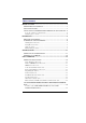
Table of Content BEFORE YOU START ...............................................................................1 CONVENTIONS OF THIS MANUAL ..........................................................1 SAFETY PRECAUTIONS ........................................................................1 THINGS YOU MUST REMEMBER BEFORE WORKING ON YOUR COMPUTER ..4 Let your computer acclimate itself .......................................................... 4 Suitable place to work .....................................
Precautions for Handling CD-ROM/DVD-ROM/Combo Drive/DVDRW/DVD+RW/DVD-Dual Discs........................................................... 18 Loading a Disc ...................................................................................... 19 USING THE WINDOWS ........................................................................19 Help Windows ....................................................................................... 19 Desktop.............................................................
TROUBLESHOOTING ..............................................................................55 CHECKING CABLES AND CONNECTIONS ..............................................55 GENERAL PROBLEMS ........................................................................56 SPECIFICATION .....................................................................................
Canadian DOC Notice For Class B Computing Devices This Class B digital apparatus meets all requirements of the Canadian Interference - Causing Equipment Regulations. Cet appareil numerique de la classe B repecte toutes les exigences du Règlement sur le matèriel brouilleur du Canada. Personal Inventory This computer system is designed for years of productive and pleasurable computing. Use this section to keep notes about details of your purchase. Update this section when you add new options.
Before you Start CONVENTIONS OF THIS MANUAL Use this manual will help you get the most from your computer. ^ If you are an experienced user of computers and/or Microsoft’s Windows operating systems, you might find it useful to read the Quick Start Guide that comes along with your accessories. ^ If you are a less experienced user, you should through the manual carefully before using your system.
5. 6. 7. 8. 9. 10. 11. 12. 13. 14. 15. 16. 17. 2 Please keep this equipment from humidity. Lay this equipment on a reliable surface when installed. A drop or fall could cause injury. Make sure to use the right voltage for the power source when connecting the equipment to the power outlet. Place the power cord in such a way that people can not step on it. Do not place anything on top of the power cord. All cautions and warnings on the equipment should be noted.
18. 19. 20. 21. ¾ The appliance coupler must have a configuration for mating with a CEE22/EN6032/IEC 320 appliance inlet. A. For U.S. and Canada: ¾ The cord set must be UL Listed and CSA Certified. ¾ The minimum specifications for the flexible cord are No. 18 AWG. B. For Japan: ¾ All components of the cord set must bear a “PSE” or “ T ” mark and registration number in accordance with the Japanese Dentori Law. ¾ The minimum specifications for the flexible cord are .75m ㎡ conductors. C.
THINGS YOU MUST REMEMBER BEFORE WORKING ON YOUR COMPUTER LET YOUR COMPUTER ACCLIMATE ITSELF Your computer can easily stand temperature extremes but it doesn’t like rapid changes in temperature, like going from the cold outdoors to a warm office. Rapid changes in temperature can cause water droplets to condense inside your case, threatening to damage the electronic parts inside.
Introduction WELCOME TO THE MINI PC Congratulations on your purchase of the Mini PC for your digital home device. The Mini PC is considered as one of the smallest Wintel personal computer in the market today. Digital Home is the new IT vision consists of interoperable devices in the home that are capable of sharing digital media across a home network.
SCENARIOS IN USING YOUR MINI PC WORKING ROOM SCENARIO In using the Mini PC in your own private study room, place it together with LCD monitor, speakers, printer/scanner/fax, modem or any other peripherals. LIVING ROOM SCENARIO In using the Mini PC in your own living room, connect it to a speaker, HDTV, DVD/VCD player, modem or any other peripherals in building your own media center at home. OFFICE SCENARIO You can also connect the Mini PC to a projector to make a presentation in a business conference.
FRONT SIDE FEATURES 1. 2. 3. 4. 5. 6. CD-ROM Release Latch Wireless LED MCE Sensor Combo Drive/DVD-Dual/DVD Super-Multi USB 2.0 Port CardReader (MMC/SD/MS) Be sure the face of the card must be facing down when inserting without using the stand or bottom side facing you when inserting using the stand. 7. 1394A TOP SIDE FEATURES 1. 2.
REAR SIDE FEATURES 1. Digital/Cable TV Connector Before connecting the cable into the connector one thing that you need to be aware of is to know the video standard being used in your country that you are viewing. This system supports 3 video standard namely: NTSC, PAL and SECAM or DVBT (Optional). 2. Modem Port Always disconnect all telephone lines from the wall outlet before servicing or disassembling this equipment. To reduce the risk of fire use only No.
7. DVI (Digital Video Interface) Connector DVI is a digital interface standard to convert analog signals into digital signals to accommodate both analog and digital monitors. 8. USB 2.0 Port 9. USB 2.0 Port 10.
Page intentionally left blank 10
Getting Started CONNECTING TO A POWER SOURCE A universal AC adapter is provided to supply your computer with power. The adapter’s AC input voltage can range anywhere from 100 to 240 volts, covering the standard voltages available in almost every country. The power cord for the AC adapter requires a three-hole grounded AC outlet. To connect the computer to an external power source: Do not use inferior extension cords as this may result in damage to your computer. The computer comes with its own AC adapter.
Never turn off or reset or move your comptuer while the hard disk is in use; doing so can result in loss or destruction of your data. Always wait at least 5 seconds after turning off your computer before turning it back on; turning the power on and off in rapid succession can damage the computer’s electrical circuitry. POWERING UP THE MINI PC At the top of the Mini PC, locate on the power button and press for a few seconds to power up the system. The Power-On Self Test (POST) runs automatically.
From the Control Panel, select and click on the “Power Options” to enter the Power Options Properties” display. Notice that there are four items namely: Power Schemes, Advanced, Hibernate, and UPS. After the installation of the driver for this system is completed, you will notice the “Away” item is added into “Power Options Properties”. In case the item is not included, we recommend you to install the driver using the support CD that comes with your system. Proceed to “Driver\QuickResume\el.all.
^ 14 A slight move on the keyboard or mouse will enter the resume mode (blue color)
Using the Mini PC CONNECTING YOUR SYSTEM VIDEO DISPLAY CONNECTION The system enables you to connect the system to different types of video display devices, like projector, LCD or traditional monitor (CRT), or TV unit. LCD OR CRT MONITOR CONNECTION You can connect the system to different types of LCD monitor. The video signal connector from the LCD monitor connects to the DVI connector through a DVI cable.
PRINTER CONNECTION You can connect the system to a USB printer. FAX/PRINTER/SCANNER CONNECTION Today’s manufacturers build the functions of printer, scanner, and fax into one unit so you connect the system to a fax/printer/scanner unit if it comes with a USB connector. SPEAKER CONNECTION The input of the speaker should be connected to the speaker output (earphone) jack.
17
THE COMBO DRIVE/DVD-DUAL/DVD SUPER-MULTI FEATURES OF THE COMBO DRIVE/DVD-DUAL/DVD SUPERMULTI The features of the Combo Drive/DVD-Dual/DVD Super-Multi drive are listed below. ^ The Audio Play feature allows you to play music CDs ^ Front panel load/unload button ^ Supports CD-DA, CD-ROM mode 1 and mode 2, MultiSession Photo CD™, CD-I/Video CD (pcs.) ^ Low power consumption ^ 12.
^ Do not use benzene, thinners, or cleaners with detergent. Only use CD-ROM/DVD-ROM cleaning kits. ^ Do not bend or drop the discs. LOADING A DISC To play a CD disc, follow the instructions listed below. Push the Combo Drive/DVD-Dual/DVD Super-Multi button on the CD drive door. Gently pull the tray all the way out. 2. Carefully lift the CD disc by the edges and make sure the shiny surface is face down (the side with no writing on it). Carefully insert the CD disc onto the tray.
DESKTOP Desktop may vary differently on the software installed in your computer with different or additional shortcuts. Recycle Bin Used for storing deleted files in case you want to recover and save it in your system. The files will only be deleted from the Recycle Bin permanently only if you empty it by right clicking your mouse and select the “Empty Recycle Bin”. Start Button Allows easy access to all Windows programs. The Start menu allows you to adapt and show the programs used most frequently.
Taskbar When you open a program, its icon is displayed at the taskbar for you to conveniently move between programs by clicking the relevant button. To add or remove toolbars from the taskbar: right click an empty spot on the taskbar, select Toolbars Î choose the toolbar you want to add. Notification The icons that appear here are for quick access to some programs and computer functions that you frequently used. For you to see the hidden icons, simply click the icon.
22
Internet Connection There are numerous ways to connect to the Internet. This may vary from the user’s working environment as well as system specifications. ^ Using a modem and a telephone line ^ Using a wired LAN ^ Using a wireless LAN (Optional) USING A MODEM FOR CONNECTION TO INTERNET ^ ^ Use a telephone line to connect to the modem port of your computer. Do not use a digital telephone line.
24 4. Select “Properties” from the popup menu that appears 5. In the “This connection uses the following items” field, select “Internet Protocol (TCP/IP), and click “Properties”.
6. Enter the system’s IP and DNS server addresses on the General tab of the “Internet Protocol (TCP/IP) Properties” window. If DHCP is used, click “Obtain an IP address automatically” and “Obtain DNS server address automatically” on the General tab.
7. After all the all the information are correctly entered in the “Internet Protocol (TCP/IP) Properties” window, click “OK” to finish. USING BOTH DHCP AND STATIC IP FOR CONNECTION TO INTERNET When you are alternatively using networks with either DHCP or static IP addressing, you can use alternative settings that enable simultaneous configurations of DHCP and static IP to use both of the network connects without reconfiguring. 1.
3. When you have completed the entire configuration, click “OK”.
USING WIRELESS LAN NETWORK FOR CONNECTION TO INTERNET (MICROSOFT’S SERVICE PACK 2) (OPTIONAL) BLUETOOTH CONNECTION Bluetooth is a developing, world wide, open, short-range radio specification focused on communication between the Internet and Net devices, plus it defines communication protocols between devices and computers. It connect wirelessly to your world: In home, at work, in motion and at play. Access the internet or your e-mail account from anywhere, anytime. Fast downloads.
Press on the Bluetooth icon to connect other devices that have this application.
Page intentionally left blank 30
Running BIOS Setup The BIOS (Basic Input and Output System) Setup program is a menu driven utility that enables you to make changes to the system configuration and tailor your system to reflect installed hardware or alter system performance. When the computer is turned back on, the system is configured with the values stored in CMOS.
THE MENU BAR The top of the screen has a menu bar with the following selections: Main - Use this menu to make changes to the basic system configuration. Advanced - Use this menu to enable and make changes to the advanced features available on your system. Security - Use this menu to set a password. The password allows bootup and controls access to the BIOS setup menu. Boot - Use this menu to configure the default system device used to locate and load the Operating System and for booting up the computer.
F9 F10 Enter Sets the parameters for the current menu to their default values. Save and Exit. Will select a sub menu or show a range of options for a field. LAUNCHING SUBMENUS Note that a right pointer symbol X appears to the left of certain fields. This pointer indicates that a submenu can be launched from this field. A submenu contains additional options for a field parameter. To call up a submenu, simply move the cursor to highlight the field and press the [Enter] key.
THE MAIN MENU When the Setup program is accessed, the following screen appears: 34
THE ADVANCED MENU Selecting Advanced from the menu bar displays the Advanced menu: 35
THE BOOT MENU The Boot menu allows the user to specify the order in which the computer is to check for a device to boot the system. You can also configure the way that the system will boot up. To make changes, select Boot from the menu bar.
THE SECURITY MENU The computer’s advanced system of security allows you to set a password to prevent unauthorized access to system resources, data, and the BIOS Setup Program.
THE EXIT MENU Once you have made all of your selections from the various menus in the Setup program, you should save your changes and exit Setup.
VGA Utilities After you have restarted Windows, open the “Control Panel” and double click on the “Display” icon. From the “Display Properties” window, select the “Settings” tab and click on the “Advanced” tab to enter the “Plug and Play Monitor on Mobile Intel® 945GM Express Chipset Family”.
40
OVERLAY SETTINGS 41
LAUNCH ZOOM 42
DISPLAY DEVICES You can adjust the right resolution for your screen display.
DISPLAY SETTINGS 44
COLOR CORRECTION 45
HOT KEYS The driver allows simultaneous outputs to CRT and TV. Before proceeding, be sure the monitor and TV are connected to the computer.
Select any key or function to replace the default key of F2 and click the “OK” button. Example: Type F8 to replace the current function key of F2 from the default mode.
Page intentionally left blank 48
Microsoft Center Edition (MCE) (Option) WINDOWS XP MEDIA CENTER EDITION (MCE) The Windows MCE is a complete software for home PC operating system for you to enjoy entertainment choices together in one place easily accessible from anywhere in the room. This will benefits the consumers to enjoy Media Center experience in their own living room. For more information on the function of the MCE, please refer to the Microsoft’s Windows XP MCE user’s guide that goes along with your software package.
50
Installing the WinXP (MCE) in AHCI System WINXP MCE INSTALLATION 1. 2. 3. Before proceeding, restart your computer and press the “DEL” key to enter the BIOS Setup. Proceed to “Advanced” Setup using the Î arrow and select the “IDE Configuration item. Set the BIOS setup IDE mode to “ATA/IDE Configuration [Enhanced] and Configure SATA as [AHCI] mode.
4. 5. 6. 7. 52 Put your floppy disk into the USB FDD drive that contain AHCI driver. (i.e.: Windows setup don’t support USB disk). Now you can start installing the WinXP MCE in AHCI mode. Press the “F6” key to load the AHCI Driver Press the “S” key in specifying to install the device for your system.
8. Select the “Intel ® 82801GBM SATA AHCI Controller (Mobile ICH7M)”. 9. The selected device will now display on the screen.
10. After installing the AHCI driver, the AHCI HDD (Mass Storage Device) is now displayed. 11. You can now follow the WinXP MCE installation process to install the Operating system. If your WinXP MCE CD still include the old IDE driver (e.g. Intel 915 Chipset or other), you will not be able to install the OS (like having blue screen or system restart). We recommend you to contact your WinXP MCE OPK CD engineer to remove the old driver and replace with a new one.
Troubleshooting This chapter describes locating and solving problems that you may encounter while using your computer. CHECKING CABLES AND CONNECTIONS Start by performing a careful visual inspection of the exterior of the computer. If no LEDs are illuminated, make sure that your computer and its peripherals are getting power and communicating with each other properly. To check the power cables, and connections: 1.
Do not substitute cables for different devices (other than the manufacturer recommended cables) even if they look exactly alike. The wiring inside the cable may be different. 7. When you are certain that you have power available and all connections are good, turn the computer on again. If the computer still does not start, you may have a hardware problem.
Specification DETAILED SPECIFICATIONS Processor ^ Intel® Yonah Duo/Solo Core, 2MB L2 Cache, up to 667MHz FSB ^ Micro-FCPGA 478 socket Operating System Compliance ^ Microsoft® Windows® XP Media Center Edition ^ Microsoft® Windows® XP Home/ Professional Edition ^ Microsoft® Windows® XP Home Edition Core Logic ^ Intel 945GT + ICH7-M (DH) Memory ^ Dual channel DDRII 533/667, memory support DMI 2GB/s link with south bridge ^ Expandable 2 slot of 200pin SO-DIMM module, 2B total memory capacity Video & Graphics ^
LED Status Indicator Power, WLAN Interface Ports ^ S-video TV out port, DC input port for External AC adapter (2-pin DC jack), DVI-I port for external analog VGA monitor & external Digital monitor, USB 2.0 port*3, MIC-In, headphone jack w/ adapter for 5.1 channel SPDIF support, Fax/Modem (internal MDC module), GigaLAN port, IEEE 1394 mini-jack, Card Reader, SDVO DVI 1.