Preface Copyright This publication, including all photographs, illustrations and software, is protected under international copyright laws, with all rights reserved. Neither this manual, nor any of the material contained herein, may be reproduced without written consent of the author. Version 1.0 Disclaimer The information in this document is subject to change without notice.
Declaration of Conformity This device complies with part 15 of the FCC rules. Operation is subject to the following conditions: • This device may not cause harmful interference. • This device must accept any interference received, including interference that may cause undesired operation.
TABLE OF CONTENTS Preface i Chapter 1 1 Introducing the Motherboard 1 Introduction...................................................................................1 Pakage Contents............................................................................1 Specifications................................................................................2 Motherboard Components..........................................................4 I/O Ports.............................................................
Chapter 4 59 Using the Motherboard Software 59 Auto-installing under Windows 7/8.............................................59 Running Setup.........................................................................59 Manual Installation..........................................................................61 Chapter 5 63 Trouble Shooting 63 Start up problems during assembly..............................................63 Start up problems after prolong use............................................
Introduction Thank you for choosing the H87H3-TI motherboard. This motherboard is a high performance, enhanced function motherboard designed to support the LGA1150 socket for Intel® 4th Generation CoreTM Family processors for high-end business or personal desktop markets. Chapter 1 Chapter 1 Introducing the Motherboard This motherboard is based on Intel® H87 Express Chipset for best desktop platform solution. It supports up to 16 GB of system memory with dual channel DDR3 1600/ 1333 MHz SO-DIMM.
Chapter 1 Specifications CPU • • LGA1150 socket for Intel ® 4 th Generation Core TM Family processors VRD 12.
• • • • 1 x ME Unlock header 1 x SATA power connector 1 x Buzzer header 1 x Consumer infrared header (CIR) 1 x Digital microphone header (For All-In-One Specification) 1 x 2 channel audio speaker header (For All-In-One Specification) 1 x LCD panel select jumper (For All-In-One Specification) 1 x LVDS connetor (For All-In-One Specification) 1 x LVDS brightness switch header (For All-In-One Specification) 1 x LVDS brightness control header (For All-In-One Specification) TPM • Embedded Nuvoton NPCT420AA0WX
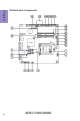
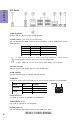
Chapter 1 4 Motherboard Components H87H3-TI USER MANUAL
LABEL 1. CPU Socket 2. F_USB COMPONENTS LGA1150 socket for Intel® 4th Generation CoreTM Family Processors Front panel USB 2.0 header Mini PCI Express slots (mini PCIe1 (full-card) supports extension cards with SATA 3. PCIE1~2 signal, USB signal and PCIe signal, and mini PCIe2 (half-card) supports extension cards with PCIe signal & USB signal.) 4. DMIC Digital microphone header (For All-In-One Specification) 5. SPKR 2 Channels audio speaker header (For All-In-One Specification) 6.
Chapter 1 I/O Ports 1. 19V DC_IN Port Connect the DC_IN port to the power adapter. 2. HDMI_IN Port (For All-In-One Specification) You can connect the HDMI output of other computer or other HDMI source to the HDMI_IN port. PC HDMI_IN port LCD_MODE button pulse Power ON Un-plugged PC LCD off Power OFF Plugged HDMI LCD off Power ON Plugged PC HDMI LCD off Power OFF Un-plugged LCD off 1.
Chapter 2 Installing the Motherboard 2-1. Safety Precautions • • • • Wear a grounding strap attached to a grounded device to avoid damage from static electricity. Discharge static electricity by touching the metal case of a safely grounded object before working on the motherboard. Leave components in the static-proof bags. Always remove the AC power by unplugging the power cord from the power outlet before installing or removing the motherboard or other hardware components.
2-3. Checking Jumper Settings This section explains how to set jumpers for correct configuration of the motherboard. Chapter 2 1. LCD_SEL: LCD panel select header (For All-In-One Specification) 1.When your panel connects to LVDS, please check LCD_SEL header setting first. 2.Due to the differences of the panel parameters, please follow the above illustration to place the jumper caps.
2. CLR_CMOS: Clear CMOS jumper Chapter 2 The following illustration shows the location of the motherboard jumpers. Pin 1 is labeled. To avoid the system instability after clearing CMOS, we recommend users to enter the main BIOS setting page to “Load Default Settings” and then “Save and Exit Setup”.
2-4. Installing Hardware 2-4-1. Installing the Processor • • Chapter 2 • • This motherboard has an LGA1150 socket. When choosing a processor, consider the performance requirements of the system. Performance is based on the processor design, the clock speed and system bus frequency of the processor, and the quantity of internal cache memory and external cache memory. You may be able to change the settings in the system Setup Utility.
Chapter 2 D. Rotate the load plate onto the package IHS (Intergraded Heat Spreader). Engage the load lever while pressing down lightly onto the load plate. Secure the load lever with the hook under retention tab. Then the cover will flick automatically. Please save and replace the cover onto the CPU socket if processor is removed.
2-4-2. Installing the CPU Cooler • • • Chapter 2 • • • Install the cooling fan in a well-lit work area so that you can clearly see the motherboard and processor socket. Avoid using cooling fans with sharp edges in case the fan casing and the clips cause serious damage to the motherboard or its components. To achieve better airflow rates and heat dissipation, we suggest that you use a high quality fan with 3800 rpm at least.
• • • • This motherboard accommodates two memory modules. It can support two 204-pin DDR3 1600/1333 MHz. Do not remove any memory module from its antistatic packaging until you are ready to install it on the motherboard. Handle the modules only by their edges. Do not touch the components or metal parts. Always wear a grounding strap when you handle the modules. You must install at least one module in any of the two slots. Total memory capacity is 16 GB.
2-4-4. Installing Add-on Cards The slots on this motherboard are designed to hold expansion cards and connect them to the system bus. Expansion slots are a means of adding or enhancing the motherboard’s features and capabilities. With these efficient facilities, you can increase the motherboard’s capabilities by adding hardware that performs tasks that are not part of the basic system.
Remove a blanking plate from the system case, and insert the wireless card into the PCIE2 slot rightwards, then tighten the screw (Please refer to Picture 1). 2 Press the metal connector of the cable into the connector on the wireless card. Ensure that the metal connector is correctly seated (Please refer to Picture 2).
2-4-5. Connecting Optional Devices Refer to the following for information on connecting the motherboard’s optional devices: Chapter 2 No. Components No. 1 SATA1~2 8 Components DMIC 2 CIR 9 F_AUDIO 3 LVDS 10 ME_UNLOCK 4 MON_SW 11 CASE 5 DISP_BRT 12 USB_TP 6 USB_CR_CAM 13 USB3F 7 F_USB -- -- 1. SATA1~2: Serial ATA III connectors SATA1~2 connectors are used to support the Serial ATA 6Gb/s device. Simpler disk drive cabling and easier PC assembly.
Chapter 2 2. CIR: Consumer infrared header 3. LVDS: LVDS connector (For All-In-One Specification) 1. You can connect the large end of the cable to the LED Panel, and connect the other small end to the slot on the motherboard. 2.Due to the chipset limitation, using dual displays LVDS(AIO) + VGA or LVDS(AIO) + HDMI will cause the problem that you may not enter BIOS setup or have the display problem.
4. MON_SW: LVDS brightness switch header (For All-In-One Specification) Chapter 2 5.
Chapter 2 6 & 12. USB_TP/USB_CR_CAM: 5-pin USB 2.0 header supports one USB 2.0 device/10-pin USB 2.0 header supports card reader and camera or other USB 2.0 devices Users please note to install the card to the correct header. 7. F_USB: Front Panel USB 2.0 header The motherboard has one USB 2.0 headers supporting two USB 2.0 ports. Additionally, some computer cases have USB 2.0 ports at the front of the case. If you have this kind of case, use auxiliary USB 2.
8. DMIC: Digital microphone header (For All-In-One Specification) Chapter 2 9. F_AUDIO: Front panel audio header The front panel audio header allows the user to install auxiliary front-oriented microphone and line-out ports for easier access. This header supports HD audio by default. If you want connect an AC’ 97 front panel audio to HD onboard headers, please set as below picture.
AC’ 97 Audio Configuration: To enable the front panel audio connector to support AC97 Audio mode. Chapter 2 If you use AC’ 97 Front Panel, please tick off the option of “ Disabled Front Panel Detect ”. If you use HD Audio Front Panel, please don’ t tick off “Disabled Front Panel Detect ” . * For reference only 10.
11. CASE: Chassis Intrusion detect header This detects if the chassis cover has been removed. This function needs a chassis equipped with instrusion detection switch and needs to be enabled in BIOS. Chapter 2 13. USB3F: Front USB 3.0 header This motherboard implements one USB 3.0 header supporting two extra front USB 3.0 ports, which delivers 5Gb/s transfer rate.
2-4-6. Installing a Hard Disk Drive/Optical Disk Drive This section describes how to install a Hard Disk Drive/Optical Disk Drive. Your motherboard features two SATA connectors supporting a total of two drives. SATA refers to Serial ATA (Advanced Technology Attachment) is the standard interface for the IDE hard drives which are currently used in most PCs. These connectors are well designed and will only fit in one orientation.
2-4-7. Connecting Case Components After you have installed the motherboard into a case, you can begin connecting the motherboard components. Refer to the following: Chapter 2 No. Components No. 1 SYS_FAN 4 Components BZ 2 CPU_FAN 5 SPKR 3 F_PANEL 6 SATA_PWR 1 & 2 . SYS_FAN (System cooling FAN connector) &CPU_FAN (CPU cooling FAN connector) Connect the CPU cooling fan cable to CPU_FAN. Connect the system cooling fan connector to SYS_FAN.
3. F_PANEL: Front panel header Chapter 2 The front panel header (F_PANEL) provides a standard set of switch and LED headers commonly found on ATX or Micro ATX cases. Hard Drive Activity LED Connecting pins 1 and 3 to a front panel mounted LED provides visual indication that data is being read from or written to the hard drive. For the LED to function properly, an IDE drive should be connected to the onboard IDE interface.
4. BZ: Buzzer header Chapter 2 5. SPKR: 2 Channel audio speaker header (For All-In-One Specification) Connect the case speaker cable to SPKR.
Chapter 2 6. SATA_PWR: SATA power connector This concludes Chapter 2. The next chapter covers the BIOS.
Memo Chapter 2 28 H87H3-TI USER MANUAL
Chapter 3 Using BIOS About the Setup Utility The BIOS (Basic Input and Output System) Setup Utility displays the system’s configuration status and provides you with options to set system parameters. The parameters are stored in battery-backed-up CMOS RAM that saves this information when the power is turned off. When the system is turned back on, the system is configured with the values you stored in CMOS.
Resetting the Default CMOS Values When powering on for the first time, the POST screen may show a “CMOS Settings Wrong” message. This standard message will appear following a clear CMOS data at factory by the manufacturer. You simply need to Load Default Settings to reset the default CMOS values. Note: Changes to system hardware such as different CPU, memories, etc. may also trigger this message. Chapter 3 Using BIOS When you start the Setup Utility, the main menu appears.
BIOS Navigation Keys The BIOS navigation keys are listed below: KEY ESC FUNCTION Exits the current menu Enter Select F1 General Help F2 Previous Value F3 Optimized Defaults F4 Save & Exit 1. For the purpose of better product maintenance, the manufacture reserves the right to change the BIOS items presented in this manual. The BIOS setup screens shown in this chapter are for reference only and may differ from the actual BIOS. Please visit the manufacture’s website for updated manual. 2.
Main Menu This menu shows the information of BIOS and enables you to set the system language, date and time. Main Advanced Chipset Tweak System Date System Time Security Exit Choose the system default language BIOS Information System Language Boot English Thu 05/23/2013 00:11:26 Chapter 3 : Select Screen /Click: Select Item Enter/Dbl Click : Select +/- : Change Opt.
Advanced Menu The Advanced menu items allow you to change the settings for the CPU and other system.
LAN Configuration The item in the menu shows the LAN-related information that the BIOS automatically detects. Main Advanced Chipset Tweak Boot LAN Configuration Onboard LAN Controller Security Enabled Chapter 3 : Select Screen /Click: Select Item Enter/Dbl Click : Select +/- : Change Opt. F1: General Help F2: Previous Values F3: Optimized Defaults F4: Save & Exit ESC/Right Click: Exit Onboard LAN Controller (Enabled) Use this item to enable or disable the Onboard LAN.
PC Health Status On motherboards support hardware monitoring, this item lets you monitor the parameters for critical voltages, temperatures and fan speeds. Main Advanced Chipset Tweak Boot Security Exit PC Health Status : : : : : : 55 51oC 1635 RPM 1639 RPM 1.760V 1.496V : Select Screen TCC Activation Temperature (DTS) 100 /Click: Select Item Enter/Dbl Click : Select +/- : Change Opt.
Power Management Setup This page sets up some parameters for system power management operation. Main Advanced Chipset Tweak Boot Security Exit About Resume by Ring Power Management Setup Resume By RING Resume By PME Resume By USB Resume By RTC Alarm EUP Function Disabled Disabled Disabled Disabled Enabled : Select Screen /Click: Select Item Chapter 3 Enter/Dbl Click : Select +/- : Change Opt.
ACPI Settings The item in the menu shows the highest ACPI sleep state when the system enters suspend. Advanced Chipset Tweak Boot ACPI Sleep State S3 (Suspend to RAM) Security Exit Select the highest ACPI sleep state the system will enter when the SUSPEND button is pressed. : Select Screen /Click: Select Item Enter/Dbl Click : Select +/- : Change Opt.
CPU Configuration The item in the menu shows the CPU configuration. Main Advanced Chipset Tweak Boot CPU Configuration Genuine Intel(R) CPU 0000 @ 2.
Active Processor Cores (All) Use this item to control the number of active processor cores. Limit CPUID Maximum (Disabled) Use this item to enable or disable the maximum CPUID value limit. You can enable this to prevent the system from “rebooting” when trying to install Windows NT 4.0. Intel Virtualization Technology (Disabled) When disabled, a VMM cannot utilize the additional hardware capabilities provided by Vandor Pool Technology.
SATA Configuration Use this item to show the mode of serial SATA configuration options. Main Advanced Chipset Tweak Boot SATA Configuration Security Exit Determines how SATA controller(s) operate.
Trusted Computing Use this item to show the information of trusted computing configuration. Advanced Current Status Information TPM Enabled Status: TPM Active Status: TPM Owner Status: Chipset Tweak Boot Enabled Disabled None Disabled Deactivated Owned Security Exit Enables or Disables BIOS support for security device. O.S. will show Security Device. TCG EFI protocol and INT1A interface will not be available. : Select Screen /Click: Select Item Enter/Dbl Click : Select +/- : Change Opt.
USB Configuration Use this item to show the information of USB configuration. Main Advanced Chipset Tweak Boot USB Configuration Security Exit USB Support Parameters All USB Devices Enabled Legacy USB Support Enabled : Select Screen /Click: Select Item Chapter 3 Enter/Dbl Click : Select +/- : Change Opt. F1: General Help F2: Previous Values F3: Optimized Defaults F4: Save & Exit ESC/Right Click: Exit All USB Devices (Enabled) Use this item to enable or disable all USB devices.
Intel(R) Rapid Start Technology Use this item to show the information of Intel(R) Rapid Start Technology. Advanced Chipset Intel(R) Rapid Start Technology Tweak Boot Disabled Security Exit Enable or disable Intel(R) Rapid Start Technology : Select Screen /Click: Select Item Enter/Dbl Click : Select +/- : Change Opt.
Intel(R) Smart Connect Technology Use this item to show the information of Intel(R) Smart Connect Technology. Main Advanced ISCT Configuration Chipset Tweak Boot Disabled Security Chapter 3 : Select Screen /Click: Select Item Enter/Dbl Click : Select +/- : Change Opt. F1: General Help F2: Previous Values F3: Optimized Defaults F4: Save & Exit ESC/Right Click: Exit ISCT Configuration (Disabled) Use this item to enable or disable ISCT configuration.
Super IO Configuration Use this item to show the information of Super IO configuration. Advanced Chipset Tweak Boot Security Exit Set Parameters of CIR Controller (CIR) F71808A Super IO Chip CIR Controller Configuration F71808A : Select Screen /Click: Select Item Enter/Dbl Click : Select +/- : Change Opt. F1: General Help F2: Previous Values F3: Optimized Defaults F4: Save & Exit ESC/Right Click: Exit F71808A Super IO Chip (F71808A) This item shows the information of the super IO chip.
Intel ME BIOS Extension Configuration Use this item to show the information of Intel ME BIOS Extension Configuration. Main Advanced Intel AMT BIOS Hotkey Pressed MEBx Selection Screen Chipset Tweak Boot Disabled Disabled Disabled Security Exit Enable/Disable Intel (R) Active Management Technology BIOS Extension. Note: iAMT H/W is always enabled. This option just controls the BIOS extension execution. If enabled, this requires additional firmware in the SPI device.
Chipset Menu The chipset menu items allow you to change the settings for the North Bridge chipset, South Bridge chipset and other system. Advanced Chipset Tweak Boot System Agent Configuration PCH Configuration ME Configuration Security Exit System Agent (SA) Parameters : Select Screen /Click: Select Item Enter/Dbl Click : Select +/- : Change Opt.
PCH Configuration Scroll to this item and press to view the following screen: Main Advanced Chipset Tweak PCH Configuration Restore AC Power Loss Power Off Audio Configuration Azalia HD Audio Enabled Boot Security Exit Select AC Power state when power is re-applied after a power failure. : Select Screen /Click: Select Item Chapter 3 Enter/Dbl Click : Select +/- : Change Opt.
ME Configuration Scroll to this item and press to view the following screen: Advanced Chipset Tweak Boot ME Control ME FW Version Security Exit Enable/Disable ME Firmware Enabled 9.0.1.1333 : Select Screen /Click: Select Item Enter/Dbl Click : Select +/- : Change Opt. F1: General Help F2: Previous Values F3: Optimized Defaults F4: Save & Exit ESC/Right Click: Exit ME Control (Enabled) Use this item to enable or disable the ME Firmware. ME FW Version (9.0.1.
Tweak Menu This page enables you to set the clock speed and system bus for your system. The clock speed and system bus are determined by the kind of processor you have installed in your system. Main Advanced Chipset Tweak Boot CPU OverClocking Configuration North Bridge Configuration Spread Spectrum Security Exit CPU OverClocking Configuration Tweak Enabled Chapter 3 : Select Screen Genuine Intel(R) CPU 0000 @ 2.
Chapter 3 Enhanced Intel SpeedStep Technology (Enabled) This item allows users to enable or disable the EIST (Enhanced Intel SpeedStep Technology). Turbo Mode (Enabled) This item allows you to control the Intel Turbo Boost Technology. Runtime Turbo Enable (Disabled) This item shows if CPU support runtime turbo or not. Internal PLL OverVoltage (Disabled) This item allows you to control the Internal PLL OverVoltage. Boot Performance Mode (Max Non-Turbo Perfor...
North Bridge Configuration Scroll to this item to view the following screen: Main Advanced Chipset Tweak Intel Graphics Cofiguration Graphics Core Ratio Limit Boot Security Graphics Core Ratio Limit 20 Chapter 3 : Select Screen /Click: Select Item Enter/Dbl Click : Select +/- : Change Opt. F1: General Help F2: Previous Values F3: Optimized Defaults F4: Save & Exit ESC/Right Click: Exit Graphics Core Ratio Limit (20) This item allows you to control the internal GFX core ratio.
Spread Spectrum (Enabled) If you enable spread spectrum, it can significantly reduce the EMI (Electro-Magnetic Interference) generated by the system. Genuine Intel(R) CPU 0000 @ 2.80GHz This is display-only field and displays the information of the CPU installed in your computer. Processor Speed (2800 MHz) This item shows the current processor speed. Memory Frequency (1067 Mhz) This item shows the memory frequency.
Boot Menu This page enables you to set the keyboard NumLock state. Main Advanced Chipset Tweak Boot Boot Configuration Operation System Select Launch PXE OpROM Launch Storage OpROM Windows 7 or other OS Disabled Enabled Chapter 3 Fast Boot Disabled Bootup NumLock State Boot mode select On LEGACY Set Boot Priority Boot Option #1 Boot Option #2 Boot Option #3 Boot Option #4 Boot Option #5 Boot Option #6 Boot Option #7 Hard Disk CD/DVD USB/Floppy USB CD/DVD USB Hard Disk: Gener i...
Security Menu This page enables you to set setup administrator password and user password. Main Advanced Chipset Administrator Password Status User Password Status Tweak Boot Security Exit Not Install Not Install Set Administrator Password Setup Disabled : Select Screen /Click: Select Item Enter/Dbl Click : Select +/- : Change Opt.
Exit Menu This page enables you to exit system setup after saving or without saving the changes. Main Advanced Chipset Save Changes and Exit Discard Changes and Exit Save Changes and Exit Discard Changes and Reset Chapter 3 Save Options Save Changes Discard Changes Restore Defaults Save as User Defaults Restore User Defaults Boot Override Generic-Multi-Card 1.00 Tweak Boot Security Exit Exit system setup after saving changes.
Updating the BIOS 1 If your motherboard has a BIOS protection jumper, change the setting to allow BIOS flashing. 2 If your motherboard has an item called Firmware Write Protect in Advanced BIOS features, disable it. (Firmware Write Protect prevents BIOS from being overwritten.) 3 Prepare a bootable device or create a bootable system disk. (Refer to Windows online help for information on creating a bootable system disk.) 4 Download the Flash Utility and new BIOS file from the manufacturer’s Web site.
Memo Chapter 3 58 H87H3-TI USER MANUAL
Chapter 4 Using the Motherboard Software Auto-installing under Windows 7/8 The auto-install DVD-ROM makes it easy for you to install the drivers and software. The support software DVD-ROM disc loads automatically under Windows 7/8. When you insert the DVD-ROM disc in the DVD-ROM drive, the auto-run feature will automatically bring up the installation screen. The screen has four buttons on it: Setup, Utilities, Browse CD and Exit. Click “Exit” button to close the Auto-Setup window.
Click Next. The following screen appears: 3. Check the box next to the items you want to install. The default options are recommended. 4. Click Next to run the Installation Wizard. An item installation screen appears: 5. Follow the instructions on the screen to install the items. Chapter 4 2. Drivers and software are automatically installed in sequence. Follow the onscreen instructions, confirm commands and allow the computer to restart a few times to complete the installation.
Manual Installation Chapter 4 Windows 7/8 will appear below UAC (User Account Control) message after the system restart. You must select “Yes” to install the next driver. Continue this process to complete the drivers installation. If the auto-install DVD-ROM does not work on your system, you can still install drivers through the file manager for your OS (for example, Windows Explorer). Look for the chipset and motherboard model, and then browse to the directory and path to begin installing the drivers.
Memo Chapter 4 62 H87H3-TI USER MANUAL
Chapter 5 Trouble Shooting Start up problems during assembly After assembling the PC for the first time you may experience some start up problems. Before calling for technical support or returning for warranty, this chapter may help to address some of the common questions using some basic troubleshooting tips. a) System does not power up and the fans are not running. 1. Disassemble the PC to remove the VGA adaptor card, DDR memory, LAN, USB and other peripherals including keyboard and mouse.
Start up problems after prolong use After a prolong period of use your PC may experience start up problems again. This may be caused by breakdown of devices connected to the motherboard such as HDD, CPU fan, etc. The following tips may help to revive the PC or identify the cause of failure. 1. Clear the CMOS values using the CLR_CMOS jumper. Refer to CLR_CMOS jumper in Chapter 2 for Checking Jumper Settings in this user manual. When completed, follow up with a Load Optimised Default in the BIOS setup. 2.
65 If fail, contact RMA CLR CMOS and restart. Yes Halt at POST screen Yes Check if monitor has display Yes Check if Power Supply Unit (PSU) is working Power Bu on is pressed but PC fails to start. - need to CLRCMOS. HDD problem.
Memo Chapter 5 66 H87H3-TI USER MANUAL